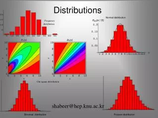
Fading Distributions
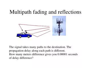
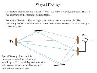
Fading Distributions. Describes how the received signal amplitude changes with time. Remember that the received signal is combination of multiple signals arriving from different directions, phases and amplitudes.


Fading Distributions
E N D
Presentation Transcript
Fading Distributions • Describes how the received signal amplitude changes with time. • Remember that the received signal is combination of multiple signals arriving from different directions, phases and amplitudes. • With the received signal we mean the baseband signal, namely the envelope of the received signal (i.e. r(t)). • Its is a statistical characterization of the multipath fading. • Two distributions • Rayleigh Fading • Ricean Fading Mudassar Ali
Rayleigh and Ricean Distributions • Describes the received signal envelope distribution for channels, where all the components are non-LOS: • i.e. there is no line-of–sight (LOS) component. • Describes the received signal envelope distribution for channels where one of the multipath components is LOS component. • i.e. there is one LOS component. Mudassar Ali
Ricean Distribution • When there is a stationary (non-fading) LOS signal present, then the envelope distribution is Ricean. • The Ricean distribution degenerates to Rayleigh when the dominant component fades away. Mudassar Ali
Modulation Techniques for Mobile Radio Lecture 7 Mudassar Ali
What is modulation • Modulation is the process of encoding information from a message source in a manner suitable for transmission • It involves translating a baseband messagesignal to a bandpass signal at frequencies that are very high compared to the baseband frequency. • Baseband signal is called modulating signal • Bandpass signal is called modulated signal Mudassar Ali
Modulation Techniques • Modulation can be done by varying the • Amplitude • Phase, or • Frequency of a high frequency carrier in accordance with the amplitude of the message signal. • Demodulation is the inverse operation: extracting the baseband message from the carrier so that it may be processed at the receiver. Mudassar Ali
Analog/Digital Modulation • Analog Modulation • The input is continues signal • Used in first generation mobile radio systems such as AMPS in USA. • Digital Modulation • The input is time sequence of symbols or pulses. • Are used in current and future mobile radio systems Mudassar Ali
Goal of Modulation Techniques • Modulation is difficult task given the hostile mobile radio channels • Small-scale fading and multipath conditions. • The goal of a modulation scheme is: • Transport the message signal through the radio channel with best possible quality • Occupy least amount of radio (RF) spectrum. Mudassar Ali
Frequency versus Amplitude Modulation • Frequency Modulation (FM) • Most popular analog modulation technique • Amplitude of the carrier signal is kept constant (constant envelope signal), the frequency of carrier is changed according to the amplitude of the modulating message signal; Hence info is carried in the phase or frequency of the carrier. • Has better noise immunity: • atmospheric or impulse noise cause rapid fluctuations in the amplitude of the received signal • Performs better in multipath environment • Small-scale fading cause amplitude fluctuations as we have seen earlier. • Can trade bandwidth occupancy for improved noise performance. • Increasing the bandwith occupied increases the SNR ratio. • The relationship between received power and quality is non-linear. • Rapid increase in quality for an increase in received power. • Resistant to co-channel interference Mudassar Ali
Amplitude Modulation (AM) • Changes the amplitude of the carrier signal according to the amplitude of the message signal • All info is carried in the amplitude of the carrier • There is a linear relationship between the received signal quality and received signal power. • AM systems usually occupy less bandwidth then FM systems. • AM carrier signal has time-varying envelope. Mudassar Ali
Amplitude Modulation • The amplitude of high-carrier signal is varied according to the instantaneous amplitude of the modulating message signal m(t). AM Modulator m(t) sAM(t) Mudassar Ali
Modulation Index of AM Signal For a sinusoidal message signal Index is defined as: SAM(t) can also be expressed as: g(t) is called the complex envelope of AM signal. Mudassar Ali
AM Modulation/Demodulation Source Sink Wireless Channel Modulator Demodulator Baseband Signal with frequency fm (Modulating Signal) Bandpass Signal with frequency fc (Modulated Signal) Original Signal with frequency fm fc >> fm Mudassar Ali
AM Modulation - Example 1/fmesg 1/fc Mudassar Ali
Angle Modulation • Angle of the carrier is varied according to the amplitude of the modulating baseband signal. • Two classes of angle modulation techniques: • Frequency Modulation • Instantanoues frequency of the carrier signal is varied linearly with message signal m(t) • Phase Modulation • The phaseq(t) of the carrier signal is varied linearly with the message signal m(t). Mudassar Ali
FM Example: 4 0 - + - - + 1.5 0.5 1 2 -4 Message signal FM Signal Carrier Signal Mudassar Ali
FM Index W: the maximum bandwidth of the modulating signal Df: peak frequency deviation of the transmitter. Am: peak value of the modulating signal Example: Given m(t) = 4cos(2p4x103t) as the message signal and a frequency deviation constant gain (kf) of 10kHz/V; Compute the peak frequency deviation and modulation index! Answer: fm=4kHz Df = 10kHz/V * 4V = 40kHz. bf = 40kHz / 4kHz = 10 Mudassar Ali
FM Demodulator • Convert from the frequency of the carrier signal to the amplitude of the message signal • FM Detection Techniques • Slope Detection • Zero-crossing detection • Phase-locked discrimination • Quadrature detection Mudassar Ali
Digital Modulation • The input is discrete signals • Time sequence of pulses or symbols • Offers many advantages • Robustness to channel impairments • Easier multiplexing of variuous sources of information: voice, data, video. • Can accommodate digital error-control codes • Enables encryption of the transferred signals • More secure link Mudassar Ali
Digital Modulation The modulating signal is respresented as a time-sequence of symbols or pulses. Each symbol has m finite states: That means each symbol carries n bits of information where n = log2mbits/symbol. ... Modulator 0 1 2 3 T One symbol (has m states – voltage levels) (represents n = log2m bits of information) Mudassar Ali
Factors that Influence Choice of Digital Modulation Techniques • A desired modulation scheme • Provides low bit-error rates at low SNRs • Power efficiecny • Performs well in multipath and fading conditions • Occupies minimum RF channel bandwidth • Bandwidth efficieny • Is easy and cost-effective to implement • Depending on the demands of a particular system or application, tradeoffs are made when selecting a digital modulation scheme. Mudassar Ali
Power Efficiency of Modulation • Power efficiency is the ability of the modulation technique to preserve fidelity of the message at low power levels. • Usually in order to obtain good fidelity, the signal power needs to be increased. • Tradeoff between fidelity and signal power • Power efficiency describes how efficient this tradeoff is made Eb: signal energy per bit N0: noise power spectral density PER: probability of error Mudassar Ali
Bandwidth Efficiency of Modulation • Ability of a modulation scheme to accommodate data within a limited bandwidth. • Bandwidth efficiency reflect how efficiently the allocated bandwidth is utilized R: the data rate (bps) B: bandwidth occupied by the modulated RF signal Mudassar Ali
Shannon’s Bound There is a fundamental upper bound on achievable bandwidth efficiency. Shannon’s theorem gives the relationship between the channel bandwidth and the maximum data rate that can be transmitted over this channel considering also the noise present in the channel. Shannon’s Theorem C: channel capacity (maximum data-rate) (bps) B: RF bandwidthS/N: signal-to-noise ratio (no unit) Mudassar Ali
Tradeoff between BW Efficiency and Power Efficiency • There is a tradeoff between bandwidth efficiency and power efficiency • Adding error control codes • Improves the power efficiency • Reduces the requires received power for a particular bit error rate • Decreases the bandwidth efficiency • Increases the bandwidth occupancy • M-ary keying modulation • Increases the bandwidth efficiency • Decreases the power efficiency • More power is requires at the receiver Mudassar Ali
Example: • SNR for a wireless channel is 30dB and RF bandwidth is 200kHz. Compute the theoretical maximum data rate that can be transmitted over this channel? Mudassar Ali
Example: • SNR for a wireless channel is 30dB and RF bandwidth is 200kHz. Compute the theoretical maximum data rate that can be transmitted over this channel? • Answer: Mudassar Ali
Noiseless Channels and Nyquist Theorem For a noiseless channel, Nyquist theorem gives the relationship between the channel bandwidth and maximum data rate that can be transmitted over this channel. Nyquist Theorem C: channel capacity (bps) B: RF bandwidth m: number of finite states in a symbol of transmitted signal Example: A noiseless channel with 3kHz bandwidth can only transmit maximum of 6Kbps if the symbols are binary symbols. Mudassar Ali
Binary Phase Shift Keying • Use alternative sine wave phase to encode bits • Phases are separated by 180 degrees. • Simple to implement, inefficient use of bandwidth. • Very robust, used extensively in satellite communication. Q 0 State 1 State Mudassar Ali
BPSK Example 1 1 0 1 0 1 Data Carrier Carrier+ p BPSK waveform Mudassar Ali
Quadrature Phase Shift Keying • Multilevel Modulation Technique: 2 bits per symbol • More spectrally efficient, more complex receiver. • Two times more bandwidth efficient than BPSK Q 11 State 01 State 00 State 10 State Phase of Carrier: p/4, 2p/4, 5p/4, 7p/4 Mudassar Ali
4 different waveforms -cos+sin cos+sin 11 01 00 10 cos-sin -cos-sin Mudassar Ali
Constant Envelope Modulation • Amplitude of the carrier is constant, regardless of the variation in the modulating signal • Better immunity to fluctuations due to fading. • Better random noise immunity • Power efficient • They occupy larger bandwidth Mudassar Ali
Frequency Shift Keying (FSK) • The frequency of the carrier is changed according to the message state (high (1) or low (0)). Continues FSK Integral of m(x) is continues. Mudassar Ali
FSK Example Data 1 1 0 1 FSK Signal Mudassar Ali