CSC-2700 – (3) Introduction to Robotics
150 likes | 248 Vues
CSC-2700 – (3) Introduction to Robotics. Robotics Research Laboratory Louisiana State University. What we learned in last class. Digital Output 8 * 8 LED matrix Techniques for LEDs control on LED matrix Basic I/O operation Define pins on PORTas either input or output ( DDRx )

CSC-2700 – (3) Introduction to Robotics
E N D
Presentation Transcript
CSC-2700 – (3) Introduction to Robotics Robotics Research Laboratory Louisiana State University
What we learned in last class • Digital Output • 8 * 8 LED matrix • Techniques for LEDs control on LED matrix • Basic I/O operation • Define pins on PORTas either input or output (DDRx) • Output control ( PORTx) • Input read (PINx) • Digital input • Button • Button Flag
How to read only specific PIN on PORT • Ex) bitwise operations Let’s assume that we add 4 buttons on PINA4 ~ 7 and 4 LEDs on PINA0~3 LED0 PIN0, LED1 1, LED2 2, LED3 3 button0 PIN4, button1 PIN5, button2 PIN6, button3 PIN7 DDRA = 0x0F (0b00001111) : PINA0 ~3= output, PIN4~7 = input PORTA = 0xF0 (0b11110000) : pull up from PIN4 to 7 for input PINA = 0xF0 (0b11110000): initial status of PINA All LEDs are off, all buttons are released If LED2 is only need to be on PORTA = PORTA | 0x04 ( 0b00000100 ) PINA == 0xF4 ( 0b11110100 ) Then, if only button2 is need to be read PINA & 0x04 ( 0b01000000 ) Button2 released: PINA ( 0b11110100 ) & 0x40 ( 0b01000000 ) 0x40 (0b01000000)
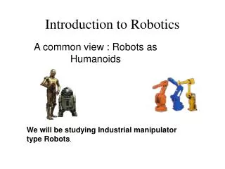
Topics for today • Pulse-width Modulation • What for • How it works • Applications • How to make it • Servo Motor Control • What is servo motor • How it works • Set position of servo head • Simple Hexabot • Walking • Turning • Control hexbot
Pulse-width Modulation • What is it? • Controlling power to inertial electrical devices • Average voltage and current controlled by turning switch • What for? • Modern electronic power switches • The main advantage of PWM is that power loss in the switching devices is very low • Relatively low cost
Pulse-width Modulation • Applications • Fans • Pumps • Robotic Servo • Stepper Motor • Telecommunication
Pulse-width Modulation • How to make it? • Digital Out (PINx) • Special Function I/O Regiser (SFR/SFIOR) • Using a main program • ns_spin( intdelay_time ) ; TOGGLE_PIN(PINxx) • Using interrupts • Timers • PORTB – PINB5 (OCA1), PINB6 (OC1B), PINB7 (OC2) • PORTE – PINE3 (OC3C), PINE4 (OC3B), PINE5 (OC3A)
Power Control (LED brightness) • How to set position of servo head • /home/csc2700/csc2700/10-PWM-dimLight-01 ICR3 = 40000u; // input capture register // pulse cycle (every 40 milli-second) TCNT3 = 0; // interrupt flag register // Set the WGM mode & prescalar TCCR3A = ( 1 << WGM31 ) | ( 0 << WGM30 ) | // timer control register ( 1 << COM3A1 ) | ( 1 << COM3B1 ) | ( 1 << COM3C1 ); TCCR3B = ( 1 << WGM33 ) | ( 1 << WGM32 ) | // timer control register TIMER3_CLOCK_SEL_DIV_8; DDRE |= (( 1 << 3 ) | ( 1 << 4 ) | ( 1 << 5 )); // I/O control register uint16_t count = 0; while (1){ OCR3A = count++; // 0 ~ 65535 (pulse width), PINE3 us_spin(200); }
Servo Motor Control • What is it? • Robotic Arms, RC-Airplane, etc. • Mechanical position change • How does it work? • Position Reader (Potentiometer) • DC-Motor • PWM DC-Motor Controller • Body Frame • Gears • Servo Head
Servo Motor Control • How to set position of a servo head • /home/csc2700/csc2700/10-PWM-Servo-01 intcount = 0; while (1){ switch (count++ % 4){ case(0): OCR3A = 1000; break; // OCR3A is PINE3 , 1000 is 1ms == left (0 degree) case(1): OCR3A = 3000; break; // OCR3A is PINE3 , 3000 is 3ms == middle (90 degree) case(2): OCR3A = 5000; break; // OCR3A is PINE3 , 5000 is 5ms == right (180 degree) case(3): OCR3A = 3000; break; // OCR3A is PINE3 } ms_spin(1000); }
Simple Hexabot • How to make it • ATmega128 Stamp Board • Three servo motors • 3 wires (18 or 19 gauge, 12’ * 3) • Battery (V 5.0)
Simple Hexabot • Let’s make it walk • /home/csc2700/csc2700/10-PWM-HexaBot-01/ intcount = 0; while (1){ LED_OFF(COL0_3x3);LED_OFF(COL1_3x3);LED_OFF(COL2_3x3); switch (count++ % 4){ case(0): SetPWM( PWM_PINE3, RIGHT_FRONT); SetPWM( PWM_PINE4, LEFT_BACK); SetPWM( PWM_PINE5, MID_RIGHT); break; case(1): SetPWM( PWM_PINE3, RIGHT_BACK); SetPWM( PWM_PINE4, LEFT_FRONT); SetPWM( PWM_PINE5, MID_RIGHT); break; case(2): SetPWM( PWM_PINE3, RIGHT_BACK); SetPWM( PWM_PINE4, LEFT_FRONT); SetPWM( PWM_PINE5, MID_LEFT); break; case(3): SetPWM( PWM_PINE3, RIGHT_FRONT); SetPWM( PWM_PINE4, LEFT_BACK); SetPWM( PWM_PINE5, MID_LEFT); break; } ms_spin(100); } #define PWM_PINE3 0 #define PWM_PINE4 1 #define PWM_PINE5 2 #define MID_RIGHT 1300 #define MID_LEFT 1700 #define RIGHT_FRONT 1700 #define RIGHT_BACK 1300 #define LEFT_FRONT 1300 #define LEFT_BACK 1700 void SetPWM( uint8_t pwmNum, uint16_t pulseWidthUSec ){ uint16_t pulseWidthTicks = pulseWidthUSec * 2; // Convert to ticks; switch ( pwmNum ){ case PWM_PINE3: OCR3A = pulseWidthTicks; break; case PWM_PINE4: OCR3B = pulseWidthTicks; break; case PWM_PINE5: OCR3C = pulseWidthTicks; break; } } // SetPWM
Motion planning of simple hexabot • What is a motion in robotics? • Sequence of specific poses with durationㄴ • What motions the simple hexabot can take? • Forward • Backward • Left turn • Right turn • ???
Homework-5 • Create a LED brightness control program, which has a plus button and a minus button • The plus button is for increasing brightness of LEDs • The minus button is for decreasing brightness of LEDs • (bonus) make a simple hexabot control program using 4 buttons • Forward button, backward button, left turn button right turn button