Understanding Image Segmentation Techniques for Data Representation
Learn about boundary following, chain codes, connected components, and region properties in image segmentation. Discover how segmentation techniques yield representative data for computational analysis. Explore algorithms for extracting boundaries and property calculation.


Understanding Image Segmentation Techniques for Data Representation
E N D
Presentation Transcript
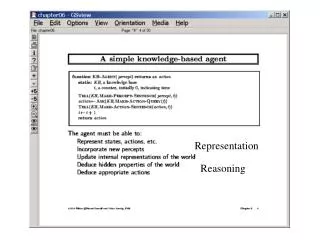
Representation The segmentation techniques yield data in the form of pixels along a boundary or pixels contained in a region. It is standard practice to use schemes that compact the segmented data into representations that facilitate the computation of descriptors.
Boundary Following: We assume (1) that we are working with binary images in which object and background points are labeled 1 and 0, respectively (2) the images are padded with a border of 0s to eliminate the possibility of an object merging with the image border.
Given a binary region R or its boundary, an algorithm for following the border of R, or the given boundary, consists of the following steps: Let the starting point, b0, be the uppermost, leftmost point in the image that is labeled 1. Denote by c0 the west neighbor of b0. Clearley, c0 always is a background point. Examine the 8-neighbors of b0, starting at c0 and proceeding in clockwise direction. Let b1 denote the first neighbor encountered whose value is 1, and let c1 be the (background) point immediately preceding b1 in the sequence. Store the location of b0 and b1 for use in Step 5.
Let b=b1 and c=c1 Let the 8-neighbors of b, starting at c and proceeding in a clockwise direction, be denoted by n1,n2,...,n8. Find the first nk labeled 1. Let b=nk and c=nk-1 Repeat Step 3 and 4 until b=b0 and the boundary point found is b1. The sequence of b points found when the algorithm stops constitutes the set of ordered boundary points.
The boundary-following algorithm works equally well if a region, rather than its boundary, is given in Fig.11.2 That is, procedure extracts the outer boundary of a binary region. If the objective is to find the boundaries of holes in a region(these are called the inner boundaries of the region), a simple approach is to extract the holes, a simple approach is to extract and treat them as 1-valued region on a background of 0s.
Chain Codes: Chain codes are used to represent a boundary by a connected sequence of straight-line segments of specified length and direction. Typically, this representation is based on 4- or 8-connectivity of the segments. The direction of each segment is coded by using a numbering scheme, as in Fig.11.3
The chain code of boundary depends on the starting point. However, the code can be normalized with respect to starting point by a straightforward procedure. We simply treat the chain code as a circular sequence of direction numbers and redefine the starting point so that the resulting sequence of numbers forms an integer of minimum magnitude. We can normalize also for rotation (in angles that are integer multiples of the directions in Fig. 11.3) by using the first difference of the chain code instead of the code itself.
Connected Components Components are objects that share at least one common neighbor (in 4- or 8- neighborhood). Defn: A connected component labeling of binary image B is a labeled image LB in which the value of each pixel is the label of its connected component.
Region Properties Once a binary image has been processed we could obtain properties about the regions in the processed image. Some of those properties are Area, centroid, perimeter, perimeter length, circularity of the region and second circularity measure
Area and Centroid Area A = sum of all the 1-pixels in the region. Centroid [r’,c’] is the average location of the pixels in the region r’ = 1/A*Sum of all the rows in the region c’ = 1/A*Sum of all the columns in the region.
Perimeter A simple definiton of the perimeter of a region without holes i set of its interior border pixels. A pixel of a region is a border pixel if it has some neighboring pixel that is outside the region. When 8-connectivity is used to determine whether a pixel inside the region is connected to a pixel outside the region, the resulting set of perimeter pixel is 4-connected. When 4-connectivity is used to determine whether a pixel inside the region is connected to a pixel outside the region, the resulting set of perimeter pixel is 8-connected.
The length of Perimeter To compute length |P| of perimeter P, the pixels in P must be ordered in a sequence P=<(r0,c0),. . . , (rk-1,ck-1)>, each pair of successive pixels in the sequence being neighbor, including the first and last pixels.
Circularity(1): With the area A and perimeter P defined, a common measure of the circularity of the region is the length of the perimeter squared divided by the area.