Download
1 / 22
220 likes | 407 Vues
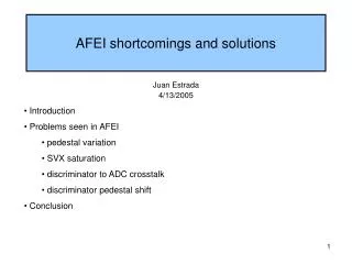
AFEI shortcomings and solutions. Introduction Problems seen in AFEI pedestal variation SVX saturation discriminator to ADC crosstalk discriminator pedestal shift Conclusion. Juan Estrada 4/13/2005. AFE and CFT. 8 photons. VLPC. 9 o K. (x512). 50 fC.

E N D
AFEI shortcomings and solutions • Introduction • Problems seen in AFEI • pedestal variation • SVX saturation • discriminator to ADC crosstalk • discriminator pedestal shift • Conclusion Juan Estrada 4/13/2005
AFE and CFT 8 photons VLPC 9o K (x512) 50 fC Central Fiber Tracker cylinder DISCR ADC Discriminator output every 396 nsec for L1 Amplitude signal readout for L3 and offline AFE
Occupancy in the detector D.Lam (online thresholds set to 1% occupancy between stores) Things will get very difficult for tracking at high luminosities.
Projected Occupancies D.Lam
Light Yield • These data show LY v. f for h=0 • Average for each supersector • “Current worst case LY” »8 pe (singlet) • This is a lower limit due to SVX sat. & ADC dynamic range • Expect Axial LY » Stereo LY • Axial Gain > Stereo Gain • SVX Sat. Effects smaller in Stereo O.Boeriu
VLPC Luminosity Dependent Effects 0, 10, 20, 30, 40 % occupancy (expect close to 40% on inner layers at highest RunII L) • As VLPC occupancy (or luminosity) goes, up QE and gain drop Gain Quantum Efficiency 20% drop 10% drop • in addition: Fiber Radiation Damage induced light yield loss (10-20%)
CFT electronics and the VLPC(introduction to the problem) AFE module (analog front end) DISCR discr. output every 396 nsec for L1 if the event is accepted at L2 send the amplitude of the signal to L3 ADC Digitized signal to L3 1 64 L2 accept SVXIIe (pipeline + ADC) AFEI is the combination of 2 custom chips (SVXIIe and SIFT). Issues: very small signals transfered from SIFT to SVX while the discriminators are firing (baseline shift) Analog signal (gain 0.5) (1..16) Discrim to L1 SIFT(1..4) (1..16) (1..16)
Tick to Tick Mean pedestal (ADC) data from the detector ~20 ADC/pe The pedestal moves up to 1 pe for the high gain pixels, this effect is much more significant in the stereo layers… This occurs because we reset the front end once per superbunch.
AFEII proto: Results • Tick to tick variation in pedestals. • Reset is identical every xing, so there should be no tick to tick variations and none is observed. xing 5, 8, 11 , 14 , 17 , 20 all 64ch from module 1 AFEII result Tick to tick variations eliminated!
Channel to Channel variation Spread with RMS=0.5 pe is typical for AFEI. With AFEI we can set only 1 zero supression threshold per SVX chip (64 channels).
AFEII proto: Results • Chan to chan variation in pedestals. • RAW ADC info (10bit) is converted inside the FPGA into 8bit SVX like data: pedestal corrected and zero suppressed. So there should be none. xing 5, all 64ch from module 1 AFEII result Chan to chan variations eliminated!
SVX Saturation (1) Event (photons produced) Reset at the beginning of the superbunch. crossing clock 1 crossing=396 ns Q1 The voltage at the input amplifiers goes up, and it can hit the maximum. After this point, the electronics can not detect any more photons until after the next reset (during the next gap). Q0
SVX saturation (2) The problem was studied in the 4 cassette test stand during summer 2004 (DØ Note 4495, P. Hasiakos). At 30% occupancy (12 crossings) • 4 Hits integrated in pipeline • “Typical” integrated charge on front end » 40 pe • 40% drop in Signal for hits in “triggered” events, on average
AFEII proto: Results • Biggest concern is SVX saturation • Test: inject huge LED pulse, measure small pulse in the same superbunch 3pe in xing 20 -> readout > 100pe in xing 5 AFEII result Saturation problem solved!
Discriminator-ADC crosstalkstudies in the test stand Discriminator to SVX crosstalk Discriminator firing in AFEI produce extra noise and shift of the analog readout. 0% discr occ. Some pedestals shift to higher values (fakes). 32% discr occ. Some pedestal shift to lower values (inefficiency). this is an event by event effect, what matters is the discriminator occupancy for the event you triggered on. Very difficult to solve. Analog information compromised. DØ Note 4500
Discriminator-ADC crosstalkconfirmation in DØ data Special runs were taken to study the effect seen in the test stand using real data. Ped shift. SVX Typical channel Ped shift. occupancy SVX This analysis was done by Avdhesh Chandra from TIFR. Chann. number
Discriminator-ADC crosstalkconfirmation in DØ data (2) • Using special runs without zero suppression, we were able to see the pedestal shift at 30% occupancy for about 11K channels. • The effect seen in the test stand is confirmed, the pedestal shift as a function of occupancy in the event has been verified. • The magnitude of the effect (from gaussian fit): mean -11, sigma 10 • 1 pe is something between 10 to 20 ADC counts. • The tails reach very far, but the 3 pe shift seen in the test stand is not typical… things like 1–2 pe shift are common.
AFEII proto: Results • Discr to ADC xtalk is not there is AFEII. The position of the pe peaks are always in the same place, and do not depend on the discriminator occupancy (compare with slide 16). AFEII result TriP results discr. on. Discr to ADC xtalk eliminated!
Discriminator pedestal shift (1) Two discriminator scans with a fixed amplitude LED signal. In one case (RED) the LED is pulsed once per turn, in the other (BLUE) the LED is pulsed in every beam crossing. When we expect the discriminator to be firing at every crossing at 25% occupancy, we see only 15% occupancy when firing on every crossing. This is equivalent to 0.5 pe shift. No effect in the same crossing. Threshold scan at 2 different amplitudes.
Discriminator pedestal shift (2) This effect depends on the zero-bias occupancy, and it is smaller than what we have seen for the Discriminator-SVX crosstalk. However, it is part of our L1 trigger… 0.6 pe could be a lot. occupancy We use a 0.6 pe (instead of the 0.5 in the previous slide) to take into account the gain reduction in the VLPC. As the occupancy goes up, so does our threshold. Efficiency per hit to the power of eight gives the tracking efficiency for 8/8. L=40E30 L=200E30
Conclusion • The current AFE has served well, but exhibits several features which limit performance: • Pedestal variation • SVX saturation • Discriminator to ADC crosstalk • Discriminator pedestal shift • Several of these undesirable features become increasingly important and the luminosity increases. • We understand the origin of these problems and the proposed electronics addresses and solves these problems by design.