Technician Licensing Class
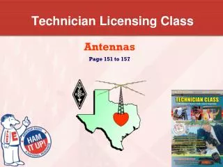
Technician Licensing Class. Antennas. Antennas. T9A3 A simple dipole mounted so the conductor is parallel to the Earth's surface is a horizontally polarized antenna. Polarization is referenced to the Earth’s surface Horizontal or Vertical. Three element beam. Simple Dipole. Antennas.

Technician Licensing Class
E N D
Presentation Transcript
Technician Licensing Class Antennas
Antennas • T9A3 A simple dipole mounted so the conductor is parallel to the Earth's surface is a horizontally polarized antenna. • Polarization is referenced to the Earth’s surface • Horizontal or Vertical Three element beam Simple Dipole
Antennas • T9A10 The strongest radiation from a half-wave dipole antenna in free space is broadside to the antenna. • T9A9 The approximate length of a 6 meter 1/2-wavelength wire dipole antenna is 112 inches. 468 f (MHz) Length of vertical in feet = _______ 112 inches (for half-wave dipole) Feet = 468/50 = 9.36 9.36 x 12 = 112.3 inches Six Meter ½ Wavelength Dipole
Antennas • T9A5 You would change a dipole antenna to make it resonant on a higher frequency by making it shorter. • T9A2 The electric field of vertical antennas is perpendicular to the Earth. Vertical and Horizontal Polarization H & V Polarized Antennas
Antennas • T9A8 The approximate length of a quarter-wavelength vertical antenna for 146 MHz is 19 inches. ______ 234 f (MHz) Length of vertical in feet = (for quarter-wave dipole) (2-meters is 144-148 MHz) Feet = 234/146 = 1.6 1.6 x 12 = 19 inches 19” Radiation Pattern of an Antenna Changes as Height Above Ground is Varied
Antennas • T9A6 Directional antennas are the quad, Yagi, and dish. • T9A1 A beam antenna concentrates signals in one direction Highest concentration of power Directional Radiation Pattern of a Yagi Beam A Beam Antenna – The Yagi Antenna
Antennas • T8C1 Radio direction finding methods are used to locate sources of noise interference or jamming. 2-element Yagi DF Antenna 3-element Quad DF Antenna
Antennas • T8C2 A directional antenna would be useful for a hidden transmitter hunt. Hidden Transmitter Hunts are called Fox Hunting All ages participate in a Fox Hunt
Antennas • T3A5 When using a directional antenna, your station might be able to access a distant repeater if buildings or obstructions are blocking the direct line of sight path by finding a path that reflects signals to the repeater. Directional Antenna used to bounce signal to reach repeater blocked by building
Antennas • T9A11 The gain of an antenna is the increase in signal strength in a specified direction when compared to a reference antenna. • T3A3 Horizontal antenna polarization is normally used for long-distance weak-signal CW and SSB contacts using the VHF and UHF bands. Isotropic Radiator Pattern “Gain” of an antenna
Antennas • T3A4 Signals could be significantly weaker if the antennas at opposite ends of a VHF or UHF line of sight radio link are not using the same polarization. Transmitter to Receiver – Radio waves from transmitting antennas induce signals in receiving antennas as they pass by
Element 2 Technician Class Question Pool Element 2 Technician Class Question Pool Antennas Valid July 1, 2010 Through June 30, 2014
T9A03 Which of the following describes a simple dipole mounted so the conductor is parallel to the Earth's surface? • A ground wave antenna • A horizontally polarized antenna • CA rhombic antenna • A vertically polarized antenna
T9A10 In which direction is the radiation strongest from a half-wave dipole antenna in free space? • Equally in all directions • Off the ends of the antenna • Broadside to the antenna • In the direction of the feedline
T9A09 What is the approximate length, in inches, of a 6 meter 1/2-wavelength wire dipole antenna? • 6 • 50 • 112 • 236
T9A05 How would you change a dipole antenna to make it resonant on a higher frequency? • Lengthen it • Insert coils in series with radiating wires • Shorten it • Add capacity hats to the ends of the radiating wires
T9A02 Which of the following is true regarding vertical antennas? • The magnetic field is perpendicular to the Earth • The electric field is perpendicular to the Earth • The phase is inverted • The phase is reversed
T9A08 What is the approximate length, in inches, of a quarter-wavelength vertical antenna for 146 MHz? • 112 • 50 • 19 • 12
T9A06 What type of antennas are the quad, Yagi, and dish? • Non-resonant antennas • Loop antennas • Directional antennas • Isotropic antennas
T9A01 What is a beam antenna? • An antenna built from aluminum I-beams • An omnidirectional antenna invented by Clarence Beam • An antenna that concentrates signals in one direction • An antenna that reverses the phase of received signals
T8C01 Which of the following methods is used to locate sources of noise interference or jamming? • Echolocation • Doppler radar • Radio direction finding • Phase locking
T8C02 Which of these items would be useful for a hidden transmitter hunt? • Calibrated SWR meter • A directional antenna • A calibrated noise bridge • All of these choices are correct
T3A05 When using a directional antenna, how might your station be able to access a distant repeater if buildings or obstructions are blocking the direct line of sight path? • Change from vertical to horizontal polarization • Try to find a path that reflects signals to the repeater • Try the long path • Increase the antenna SWR
T9A11 What is meant by the gain of an antenna? • The additional power that is added to the transmitter power • The additional power that is lost in the antenna when transmitting on a higher frequency • The increase in signal strength in a specified direction when compared to a reference antenna • The increase in impedance on receive or transmit compared to a reference antenna
T3A03 What antenna polarization is normally used for long-distance weak-signal CW and SSB contacts using the VHF and UHF bands? • Right-hand circular • Left-hand circular • Horizontal • Vertical
T3A04 What can happen if the antennas at opposite ends of a VHF or UHF line of sight radio link are not using the same polarization? • The modulation sidebands might become inverted • Signals could be significantly weaker • Signals have an echo effect on voices • Nothing significant will happen
Technician Licensing Class Feed Me withSome Good Coax!
Feed Me with Some Good Coax! • T6D11 A common use of coaxial cable is to carry RF signals between a radio and antenna. • T9B3 Coaxial cable is used more often than any other feedline for amateur radio antenna systems because it is easy to use and requires few special installation considerations. • T9B2 50 ohms is the impedance of the most commonly used coaxial cable in typical amateur radio installations. Copper Wire Insulation Outside Insulation Mesh
Feed Me with Some Good Coax! • T9B5 As the frequency of a signal passing through coaxial cable is increased the loss increases. • The Higher the frequency the more the loss • T9B7 PL-259 type coax connectors are commonly used at HF frequencies. • T9B6 A Type N connector is most suitable for frequencies above 400 MHz? BNC, Type N, and PL 259 Connectors
Feed Me with Some Good Coax! N Male N Female Male VHF PL-259 Male BNC Male SMA Female SMA Female BNC Female SO-239 Understand the type of connector on your radio You may need an adapter from your coax connector to your radio Never buy cheap coax, connectors, or adapters
Feed Me with Some Good Coax! • T7C11 A disadvantage of "air core" coaxial cable, when compared to foam or solid dielectric types is that it requires special techniques to prevent water absorption. Smaller Heliax Large coax, with hollow center conductor, low loss
Feed Me with Some Good Coax! • T7C9 The most common cause for failure of coaxial cables is moisture contamination. • Regular BNC, Type N, and PL259 connectors are not water-tight. • T9B8 Coax connectors exposed to the weather should be sealed against water intrusion to prevent an increase in feedline loss. • T7C10 The outer jacket of coaxial cable should be resistant to ultraviolet light because UV light can damage the jacket and allow water to enter the cable. • T9B10 Electrical differences exists between the smaller RG-58 and larger RG-8 coaxial cables in that RG-8 cable has less loss at a given frequency. Coax Cable Type, Size, and Loss per 100 feet Coax Type Size Loss @ 100 MHz Loss @ 400 MHz RG-58U Small 4.3 dB9.4 dB RG-8X Medium 3.7 dB 8.0 dB RG-8U Large 1.9 dB 4.1 dB RG-213 Large 1.9 dB 4.5 dB Hardline Large, Rigid 0.5 dB 1.5 dB
Feed Me with Some Good Coax! • T9B11 The lowest loss feedline at VHF and UHF is an Air-insulated hard line. • T7C2 An antenna analyzer can be used to determine if an antenna is resonant at the desired operating frequency. • T7C3 In general terms, standing wave ratio (SWR) is a measure of how well a load is matched to a transmission line. • T9B1 It is important to have a low SWR in an antenna system that uses coaxial cable feedline to provide efficient transfer of power and reduce losses. MFJ-269 SWR Analyzer Impedance Mismatch Causes Reflected Wave
Feed Me with Some Good Coax! • T7C4 A “1 to 1” reading on an SWR meter indicates a perfect impedance match between the antenna and the feedline. SWR Reading Antenna Condition 1:1 Perfectly Matched 1.5:1 Good Match 2:1 Fair Match 3:1 Poor Match 4:1 Something definitely Wrong A battery operated SWR analyzer for tower antenna work
Feed Me with Some Good Coax! • T7C5 2 to 1 is the approximate SWR value above which the protection circuits in most solid-state transmitters begin to reduce transmitter power. • T7C6 An SWR reading of 4:1 means there is an impedance mismatch. • T9B9 A loose connection in an antenna or a feedline might cause erratic changes in SWR readings. Make sure all coax connections are tight to help minimize interference
Feed Me with Some Good Coax! • T7C8 Other than an SWR meter you could use a directional wattmeter to determine if a feedline and antenna are properly matched. Single Needle Dual/Twin Needle
Feed Me with Some Good Coax! • T7C7 Power lost in a feedline is converted into heat. • T9B4 An antenna tuner matches the antenna system impedance to the transceiver's output impedance. MFJ-971 Portable QRP 200 Watt Tuner Miracle QPak 50 Watt Manual Tuner Icom 7000 with LDG 7000 Auto-Tuner Palstar 1500 Watt Auto-Tuner MFJ-994B 1500 Watt Auto-Tuner
Feed Me with Some Good Coax! • T7A7 If figure T5 represents a transceiver in which block 1 is the transmitter portion and block 3 is the receiver portion, the function of block 2 is a transmit-receive switch. 1 2 3 Transmitter Receiver T/R Switch Figure T5
Feed Me with Some Good Coax! • T7C1 The primary purpose of a dummy load is to prevent the radiation of signals when making tests. • Prevents signals from being sent out over the air • Allows observation of signal on Spectrum Analyzer Dummy Load-Can 1kw with oil 300 Watt Dry Dummy Load Dry Dummy Load
Element 2 Technician Class Question Pool Element 2 Technician Class Question Pool Feed Me with Some Good Coax! Valid July 1, 2010 Through June 30, 2014
T6D11 Which of the following is a common use of coaxial cable? • Carry dc power from a vehicle battery to a mobile radio • Carry RF signals between a radio and antenna • Secure masts, tubing, and other cylindrical objects on towers • Connect data signals from a TNC to a computer
T9B03 Why is coaxial cable used more often than any other feedline for amateur radio antenna systems? • It is easy to use and requires few special installation considerations • It has less loss than any other type of feedline • It can handle more power than any other type of feedline • It is less expensive than any other types of feedline
T9B02 What is the impedance of the most commonly used coaxial cable in typical amateur radio installations? • 8 ohms • 50 ohms • 600 ohms • 12 ohms
T9B05 What generally happens as the frequency of a signal passing through coaxial cable is increased? • The apparent SWR increases • The reflected power increases • The characteristic impedance increases • The loss increases
T9B07 Which of the following is true of PL-259 type coax connectors? • They are good for UHF frequencies • They are water tight • The are commonly used at HF frequencies • They are a bayonet type connector
T9B06 Which of the following connectors is most suitable for frequencies above 400 MHz? • A UHF (PL-259/SO-239) connector • A Type N connector • An RS-213 connector • A DB-23 connector
T7C11 What is a disadvantage of "air core" coaxial cable when compared to foam or solid dielectric types? • It has more loss per foot • It cannot be used for VHF or UHF antennas • It requires special techniques to prevent water absorption • It cannot be used at below freezing temperatures
T7C09 Which of the following is the most common cause for failure of coaxial cables? • Moisture contamination • Gamma rays • The velocity factor exceeds 1.0 • Overloading
T9B08 Why should coax connectors exposed to the weather be sealed against water intrusion? • To prevent an increase in feedline loss • To prevent interference to telephones • To keep the jacket from becoming loose • All of these choices are correct