Beam time structures 1
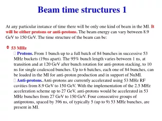
Beam time structures 1. At any particular instance of time there will be only one kind of beam in the MI. It will be either protons or anti-protons. The beam energy can vary between 8.9 GeV to 150 GeV. The time structure of the beam can be: 53 MHz

Beam time structures 1
E N D
Presentation Transcript
Beam time structures 1 • At any particular instance of time there will be only one kind of beam in the MI. It will be either protons or anti-protons. The beam energy can vary between 8.9 GeV to 150 GeV. The time structure of the beam can be: • 53 MHz • Protons. From 1 bunch up to a full batch of 84 bunches in successive 53 MHz buckets (19ns apart). The 95% bunch length varies between 1 ns, at transition and at 120 GeV after bunch rotation for anti-proton stacking, to 10 ns for single coalesced bunches. Up to 6 batches, each one of 84 bunches, can be loaded in the MI for anti-proton production and in support of NuMI. • Anti-protons. Anti-protons are currently accelerated using 53 MHz RF cavities from 8.9 GeV to 150 GeV. With the implementation of the 2.5 MHz acceleration scheme up to 27 GeV, anti-protons would be accelerated in 53 MHz bunches from 27 GeV to 150 GeV. Four consecutive groups of antiprotons, spaced by 396 ns, of typically 5 (up to 9) 53 MHz bunches, are present in MI.
Beam time structures 2 • 2.5 MHz - Protons or anti-protons • Anti-protons transfers from the Accumulator and transfers to or from the Recycler Ring instead happen in four 2.5 MHz bunches in successive 2.5 MHz RF buckets (396 ns spacing). 95% bunch lengths range from 100 to 200 ns at 8GeV. With the implementation of 2.5 MHz anti-proton acceleration, bunch lengths will shrink down to 40 ns at 27 GeV
Protons for anti-proton stacking and fixed-target Protons for Tevatron tune-up Proton transfers for collider operation
Anti-proton transfers from Accumulator/Recycler Ring Anti-proton transfers to the Tevatron
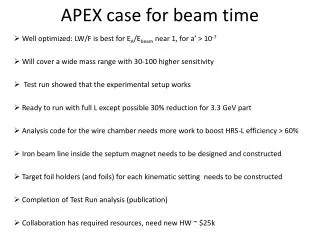
Measurements Specifications 1 • The upgraded BPM system will provide a position measurement of the beam present in the machine for each one of the operating modes described above. In particular the system should be capable of measuring beam positions with 6 batches loaded in the MI, however spaced. • The upgraded BPM system will also provide a beam intensity measurement from the magnitude of the sum of the plate signals for each BPM. This measurement will provide a “relative” intensity measurement between different BPMs. BPM-to-BPM scaling capability should be incorporated in the system to equalize the response of the different BPMs. • It is understood that during particular RF manipulations of the beam, like slip-stacking and coalescing, with no steady defined RF structure, the BPM system might not report sensible data.
Measurements Specifications 2 • The system will operate in both narrow and high bandwidth mode. • Narrow bandwidth will be used for measurements that do not need single turn resolution and represent a single ensemble position measurement of the beam present in the machine averaged over many turns (100 turns or more). • High bandwidth is needed for measurements that require single turn resolution. • The system will need to be switched between narrow and high bandwidth operations in a given cycle with a minimum interruption in data acquisition (less than ~ 10 ms).
Measurements Specifications 3 • For 2.5 MHz anti-proton transfers the system will provide a single ensemble position measurement of the beam present in the machine. No bunch-by-bunch position measurement is required in this case. • For 53 MHz multi-batch operation the system should be able to provide, if requested, a batch-by-batch measurement. The batch-by-batch measurements are only possible in high bandwidth mode and will measure one batch at a time. • The system must be able to provide first injection turn and last extraction turn for each portion of beam injected or extracted from the machine. It has to be able to cope with multiple beam injection/extraction regions and with opposite circulating directions of protons and anti-protons in the machine. • If there are multiple injections in the same cycle, the system must provide the capability to measure the first turn for each portion of beam injected in the machine. Successive injections from the Booster happen at a maximum rate of 15 Hz. • If there are multiple single turn extractions in the same cycle, the system must provide the capability to measure the extraction turn of at least one portion of beam extracted from the machine.
Measurement Definitions • Measurement range. This is defined as the range of positions, relative to the BPM center, over which the BPM measurement must be valid and meet the accuracy requirements. • Absolute position accuracy. This determines how well the position of the beam is measured with respect to the survey center-line. This is limited by a number of factors including alignment, calibration, cable attenuation and noise • Relative position accuracy. This determines how well the displacement of the beam is measured over the measurement range. This requirement does not include offset errors, but does set limits on the scale errors, non-linearities and random errors • Position resolution. This is a requirement on the smallest change in beam position that the BPM can reliably measure. • Position linearity. This is a requirement on the linearity of the BPM response to orbit changes over the measurement range. The linearity is defined as the difference between the measured BPM position and the slope of the BPM response at the center of the BPM. • Long-term position stability. This is a requirement on the BPM system ability to give the same position value for the same beam position and intensity over time. • Relative intensity accuracy. This is a requirement on the relative intensity measurements between BPMs. It is understood that during the acceleration cycle there will be, for a given BPM, apparent variations of beam intensity due to changes in bunch widths.
Measurement Types • Flash Frame:A single turn orbit measurement, performed in high bandwidth mode, associated with injection or extraction of beam. • Turn-by-turn:A measurement of the orbit on every turn (588 53 MHz RF buckets) for a specified number of turns, performed in high bandwidth mode. • Averaged orbit:An average of a specified number of turn-by-turn measurements. • Display Frame:A narrow bandwidth measurement triggered by the display frame TCLK ($7B). This measurement occurs once per cycle. • Profile frame:A narrow bandwidth measurement triggered by the profile frame TCLK ($7A). This measurement can occur up to 128 times per cycle. • Fast time plot (FTP):a narrow bandwidth measurement taken at least at 500 Hz. FTP measurements for all channels in parallel must be supported.
Acquisition Specifications • Each Main Injector cycle is uniquely identified by a machine state. This state information is transmitted on the MDAT system and is valid at the TCLK reset for the main ramp. Each state must have a unique set of readout specifications that is re-configurable by the end-user. • Injections and extractions for the Main Injector are identified by Beam Sync clock events. The BPM system must be able to collect data based on these events as defined in the state acquisition specification. • The BPM system will be directed (via the acquisition specifications) to take turn-by-turn measurements for particle injection and extraction, triggered by the relevant Beam Sync Clock event. The system must support 512 turns for each measurement. The specific turn with actual injection or extraction must occur in the corresponding dataset and the BPM system must identify the data for the first or last turn in the set. • The BPMs must provide the capability for turn-by-turn measurement at a user specified time with 2048 turns. • When in high bandwidth mode, it would be desirable, for debugging purposes, if the system would be able to respond to a self-trigger, based on beam over threshold, instead of using hard timing controls.


![Data Structures [1]](https://cdn3.slideserve.com/6547756/data-structures-1-dt.jpg)