Download
1 / 31
370 likes | 680 Vues
Fixed Ultrasonic Gas Leak Detection. Edward Naranjo Emerson Process Management, Rosemount Analytical. Presenter. Edward Naranjo Director of Marketing, Flame and Gas Ph.D. Chemical Engineering from the University of California, Santa Barbara; B.S. Chemical Engineering, Caltech

E N D
Fixed Ultrasonic Gas Leak Detection Edward Naranjo Emerson Process Management, Rosemount Analytical
Presenter • Edward Naranjo • Director of Marketing, Flame and Gas • Ph.D. Chemical Engineering from the University of California, Santa Barbara; B.S. Chemical Engineering, Caltech • ISA Orange County Section president • ISA Process Measurement and Control Division (PMCD) Director-elect
Content • Introduction • Detection Coverage • Detector Placement • Allocation • Commissioning • Maintenance • Conclusion
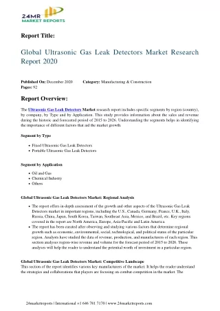
Ultrasonic Gas Leak Detection • UGLD is a detection method used to establish the presence of high pressure leaks • Well suited for open, ventilated areas • Does not require transport of gas to the sensor • Provides 360° coverage
Ultrasonic Gas Leak Detection (Continued) Because of its principle of operation, UGLD can serve as an additional and complementary means for mitigating the risk of fire and explosions1, 2 • HSE. 2004. Fire and Explosion Strategy, Issue 1. Hazardous Installations Directorate, Offshore Division. http://www.hse.gov.uk/offshore/strategy/fgdetect.htm. Downloaded October 22, 2010. • HSE. 2007. Acoustic Leak Detection. Hazardous Installations Directorate, HID Semi Permanent Circular SPC/TECH/OSD/05. http://www.hse.gov.uk/foi/internalops/hid/spc/spctosd05.htm. Downloaded October 22, 2010.
Safety in Diversity • All sensing technologies are vulnerable under certain conditions, resulting in poor detection efficiency • In a Health and Safety Executive (HSE) study, traditional fixed gas detectors accounted for 62% of all detected gas releases over nine years3, 4 • Remaining 38% of releases were mainly detected by personnel 3 HSE Offshore Technology Report – OTO 1999 079, Offshore Hydrocarbon Release Statistics, January 2000. http://www.hse.gov.uk/research/otohtm/1999/oto99079.htm. Downloaded October 18, 2010. 4 HSE Offshore Technology Report – OTO 2000 112, Offshore Hydrocarbon Release Statistics, 2000. http://www.hse.gov.uk/research/otohtm/2000/oto00112.htm. Downloaded October 22, 2010.
Diverse detection methods offer the best safeguard against fire and explosion hazards Having few common failures increases likelihood of detection on demand Safety in Diversity (Continued)
Challenges for UGLD Use • Despite UGLD’s wider acceptance, the allocation, installation, commissioning, and maintenance of ultrasonic gas leak detectors remains poorly understood • No regulatory standards and few corporate codes of practice5,6 • No guidelines on the optimal combination of point IR, open path IR detectors, and ultrasonic gas leak detectors for particular applications7 • Correspondence between a hazard defined by gas concentration and a noise level is a persistent question 5 BP. 2009. GP 30-85. Fire and Gas Detection. 6 Shell. 2002. DEP 32.30.20.11-Gen. Fire, Gas and Smoke Detection Systems. 7 HSE. 2004. Fire and Explosion Strategy, Issue 1. Hazardous Installations Directorate, Offshore Division.
Gas Leak Detection from Ultrasound Pressurised Gas Leak Frequency Range Ultrasonic Audible | 0 to 25 kHz | 25 to 100 kHz |
Leak Rate • Molecules from escaping gas produce a mixture of audible and ultrasonic noise known as broadband sound • Leak rate (or mass flow rate) is a measure of hazard severity • Directly proportional to the cross sectional area of the orifice and the pressure inside the vessel8, 9 p1 p2 A 8 Bird, R. B., Stewart, W. E., and Lightfoot, E. N. 1960. Transport Phenomena. New York: John Wiley & Sons. Ch. 15. 9 Whitaker, S. 1986. Introduction to Fluid Mechanics. Malabar, FL: Robert E. Krieger Publishing Co. Ch. 10.
Alarm threshold Safety margin SPL (dB) Ultrasonic background noise time (s) Minimum Pressure • High pressure systems must be pressurized to a minimum of 145 psi (10 bar) for UGLDs to detect a leak • At these pressures, the ultrasound generated by a leak is greater than background ultrasound emissions
30 psi (2 bar) Minimum Pressure (Continued) • Minimum pressure that supports generation of ultrasound is approximately 30 psi (2 bar) as given by • For air ( = 1.4), the critical pressure ratio is 0.53 Typical levels of ultrasonic background noise prevent use of ultrasonic detectors at such low pressures
Sound Pressure Level (SPL) • SPL varies according to the sound source’s power dWs/dt, distance to the leak r, and room constant S:10 SPL vs. distance. Methane: 0.1 kg/s, p = 47 bar (682 psi), d = 4 mm; (■) ethylene: 0.1 kg/s, p = 37 bar stance for methane and ethylene leaks. () (537 psi), d = 4 mm. Ambient background SPL ≈ 40 dB. 14 10 Raichel, D. R. 2006. The Science and Applications of Acoustics, second edition. New York: Springer.
Leak Detection Range • The detection range of an ultrasonic gas leak detector depends on the leak rate and ultrasonic background noise • Leak rate governs the ultrasonic noise level generated by the leak • In practice, most industrial plants have ultrasonic background noise levels of approximately 55 dB
Detection Coverage 16 • Leak rate = 0.1 kg/s (methane) (ea. 4 mm leak at 46 bar) • Coverage is reduced for both lower gas pressure or higher background noise
Installation • Detectors are installed at heights of 1 - 2 m above potential leak spots • Avoid shadowing or blockage by installing detectors where sound paths are unobstructed by large solid structures 1 - 2 meters
Placement of ultrasonic gas leak detectors is a function of three factors: Location of potential gas leaks Acceptable level of risk (minimum leak rate to be detected) Extraneous sources of ultrasound Likely sources of gas plumes: Valves Weld joints Flanges Gaskets Vessels Well bays Detector Placement Gas leak detector placed near potential source of leaks.
Detector Placement (Continued) • Minimum leak rates define the sensitivity required of ultrasonic gas leak detectors • A categorization of leak rates by the Health Safety Executive (HSE) provides guidance on what’s an acceptable level of risk11: 11 HSE Report. 2001. OSD Hydrocarbon Release Reduction Campaign, Report on the Hydrocarbon Release Investigation Project ~ 1/4/2000 to 31/3/2001.
Commissioning • Commissioning consists of two steps: • Test detection system with test unit • Verify system performance with leak simulation equipment
Leak Simulation • Leak simulations are performed around the expected perimeter of coverage to verify detection range • Ensure detection is unaffected by blockage and acoustic reflections Detector Nozzle
Leak simulations are performed with inert gases Similar molecular weight and specific heat ratios as target gases Leak Simulation (Continued) UGLD Response to Inert and Combustible Gas Leaks. () Methane, () Nitrogen, () Hydrogen, () Helium. Leak Rate = 0.01 kg/s. Measurement Error = 3 dB. 12 Atkins, P. W. 1986. Physical Chemistry, 3rd edition. New York: W. H. Freeman and Company. 13 Engineering Toolbox. http://www.engineeringtoolbox.com/specific-heat-ratio-d_608.html. Downloaded October 25, 2010.
Maintenance • Regular visual checks • Blockages on windscreen • Visual damage to unit • Testing by means of portable test tool
Detector Selection • Ultrasonic gas leak detectors should be sufficiently sensitive to detect gas leaks at pre-defined levels • Alarm threshold values may need to be adjusted if new sources of ultrasound are introduced close to detectors • Detectors should be equipped with electronic high pass filters to screen audible spectrum of broadband sound • Filtering background noise interference enhances immunity to false signals
Detector Selection (Continued) • Instruments equipped with fail to safe features enhance operational confidence • Example: Acoustic self check periodically verifies integrity of electronic circuitry and operation of acoustic sensor • Detectors should support analog output and two-way digital communication to integrate to emergency shutdown systems (ESDs)
Conclusions • Ultrasonic gas leak detectors offer an additional and complementary means of detecting gas leaks • Share few common failure modes with conventional gas sensors • Improve detection rate • Guidelines for UGLD allocation are simple • 360 coverage lends itself well for calculating the number and location of detectors in a room • Detection radius is influenced by ultrasonic background noise, minimum discharge rate to be detected, and ultrasonic interferences
Conclusions (Continued) • Results from several mapping surveys suggests certain process areas have similar levels of background ultrasound • Enable users to estimate detection coverage based on collected data • Examples of UGLD allocation in offshore and onshore facilities were presented • Classification of spaces into very low noise, low noise, and high noise prove useful for deciding on appropriate alarm level and detection coverage • Further fine tuning is possible by conducting a mapping survey
Conclusions (Continued) • Through commissioning users can verify leak detectors respond to leaks at a specified radius • Functional test is a close proxy of a hazard scenario • A minimum amount of maintenance must be carried out with ultrasonic gas leak detectors • Visual inspection • Testing
Conclusions (Continued) • When choosing a detector, users are advised to consider features that improve reliability and integration to ESDs • Fail to safe features and calibrators can ensure devices are operational at all times • Analog output and two-way digital communication are increasingly essential for the deployment of safety systems