Download
1 / 12
160 likes | 546 Vues
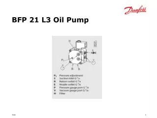
BFP 21 L3 Oil Pump. BFP 21 Two-Pipe Conversion. 071N0064. 071N0041. BFP 11 L3 Oil Pump. BFP 11 Two-Pipe Conversion. 071N0063. 071N0046. Left and Right Rotation. Oil Supply through the Pump. BHO 70 Series Control Box. New Type Remarks BHO 71.10 One-stage system

E N D
BFP 21 Two-Pipe Conversion 071N0064 071N0041
BFP 11 Two-Pipe Conversion 071N0063 071N0046
BHO 70 Series Control Box New Type Remarks BHO 71.10 One-stage system BHO 72.10 Two-stage system BHO 72.11 Two-stage system, short pre-purge/long post-ignition BHO 73.10 Two-stage system, short post-ignition (terminals 6 and 7) BHO 74.10 Two-stage burners above 30 kg/h + WLE
If a fault occurs, the burner control will lockout, this is shown by a constant red light in the press button. The reason for lockout can be read by means of flash codes in the press button. Press the button and keep it down for 5 seconds, the control will change to show flash codes. The flash code is shown at intervals of 2 seconds, to return to “reset mode” press the reset button and keep it down for 5 seconds. The control is reset by pressing the reset button shortly. Note! It is only possible to reset the control in “reset mode”. When reset, the control will try to restart, but if the fault still exists or a new one has occurred, the control will lockout again. In the event of under-voltage, the control will take up a waiting position. This is indicated by a flash code of 8 flashes from the press button. When the voltage is within the work area, the flash code stops and the control starts as normal. Setting the box to diagnostics
Diagnosis Flash Codes • False light 2 flashes • No flame when safety time elapses 3 flashes • More than three restarts in the same cycle 4 flashes • Max. waiting time on pre-heater overrun (10 min) 5 flashes • Supply voltage above 264 V a.c. 6 flashes • Supply voltage below 185 V a.c. 8 flashes
Nozzle Spray Patterns Kerosene Nozzles Standard Nozzles