Download
1 / 17
170 likes | 192 Vues
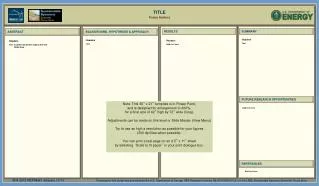
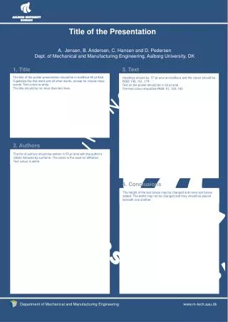
This document provides instructions for properly identifying and filling out an IEEE 802.11 submission template for PowerPoint presentations.

E N D
[place presentation subject title text here] Date: Sept 16, 2004 Author: Charles R. Wright, Azimuth Systems, Inc., Acton, MA charles_wright@azimuthsystems.com Mike Goettemoeller, Texas Instruments, Santa Rosa goette@ti.com Shravan Surineni, Qualcomm, Concord, MA shravans@qualcomm.com Areg Alimian, CMC, Santa Barbara, MA areg_alimian@aurorastar.net John Doe, Some Company
Abstract [place presentation abstract text here] John Doe, Some Company
802.11 Template Instructions 1/4 • To properly identify your PowerPoint presentation as an IEEE 802.11 Submission there are 7 steps that you must complete, and 12 data fields that you must fill in. • Step 1. Obtain a document number. • Step 2. Title slide: Fill in the presentation subject title text, full date and the full author(s) details (a total of 3 data fields). • Step 3. Abstract slide: Fill in the abstract text. • Step 4. Menu select File, Properties. Fill in the 2 data fields: • Author field = first author's name • Company field = company name John Doe, Some Company
802.11 Template Instructions 2/4 • Step 5. Menu select View, Master, Slide Master. Place the document title in the right hand side of the header. • Title example "doc.: IEEE 802.11-04/9876" , or • "doc.: IEEE 802.11-04/9876r2" • Step 6. Menu select View, Header and Footer (5 data fields): • Slide tab: • Header = venue date (Month Year) • Footer = first author, company • Notes tab: • Data and time, Fixed = venue date (Month Year) • Header = document title (e.g. “doc.: IEEE 802.11-04/9876”) • Footer = first author, company • Click "Apply to all". • Step 7. Delete the four template instruction slides. John Doe, Some Company
802.11 Template Instructions 3/4 • PowerPoint Submission Preparation Summary: • Things to do: 7 • Fields to fill in: 12 John Doe, Some Company
802.11 Template Instructions 4/4Recommendations • a) Always start a new presentation using the template, rather than using someone else's presentation. • b) For quick and easy creation of new 802.11 submissions, place the 802.11 template files in the template folder area on your computer. Typical locations are: • c:\Program Files\Microsoft Office\Templates\802.11, or • c:\Documents and Settings\User Name\Application Data\Microsoft\Templates\802.11 • To create a new submission, menu select File, New, then select the appropriate 802.11 template file. • c) When you update or revise your presentation, remember to check all 6 fields in steps 5 and 6 for the correct values. • rev: de20040722 John Doe, Some Company
Outline • Needs of the TGT users • Test environments • The metrics • Relationship of metrics to application performance John Doe, Some Company
Needs of TGT users • TGT should enable TGT users to analyze performance of their wireless devices and systems when specific network applications being run over them • Data, streaming multimedia, VoIP • TGT users need repeatable measurements • TGT users need … John Doe, Some Company
Test Environments • The block diagrams to follow are very generic and represent a starting point for discussion • It may not be obvious what each block means • Will explain after the block diagrams • The blocks are functional and does not mean that they must exist as separate equipment • Some of the blocks may not currently exist John Doe, Some Company
= RF signal path Anechoic Chamber Radiated Environment With Multipath Traffic Generator & Analyzer 802.11 Device Bidirectional Multipath Simulator DUT V.A. Adjacent Channel Intereferer V.A. Ethernet John Doe, Some Company
= RF signal path Anechoic Chamber Radiated Environment, No Multipath Traffic Generator & Analyzer 802.11 Device DUT V.A. Adjacent Channel Intereferer V.A. Ethernet John Doe, Some Company
= RF signal path Conducted Environment With Multipath Traffic Generator & Analyzer 802.11 Device Bidirectional Multipath Simulator DUT V.A. Adjacent Channel Intereferer V.A. Ethernet John Doe, Some Company
= RF signal path Conducted Environment, no Multipath Traffic Generator & Analyzer 802.11 Device DUT V.A. Adjacent Channel Intereferer V.A. Ethernet John Doe, Some Company
Open Air Environment Traffic Generator & Analyzer 802.11 Device DUT Ethernet The open air environment does not guarantee repeatable reasults, but is seen as a useful environment for some tests John Doe, Some Company
A Starting List of Metrics • Layer 2 metrics • Maximum forwarding rate, FRMOL • MSDU loss rate • Delay • Jitter • PHY layer metrics • MPDU loss rate • Rate vs. range • Needs to be fully defined • Adjacent channel, next adjacent channel interference • Needs to be fully defined • Device level • Antenna pattern • More… • AP performance metrics • Transition time (roaming) metrics • More… John Doe, Some Company
Relationship of link layer metrics to application performance • Application performance can be predicted using link layer metrics • Models exist for VoIP (ITU G.107), data • Analogous models are being developed for video in the ITU • A very limited set of standard applications (ie, non vendor-specific) may need to be measured directly • Case in point: FTP • Might mean we add another metric: data throughput • Definition to be agreed on in the group • Recognizes importance of real (not estimated) performance for this application metric John Doe, Some Company
Relationship of PHY layer and device metrics to user experience • Receiver sensitivity combined with antenna pattern determines range, given no interference • For a given channel condition and transmitter power • Defining the methodology for measuring Rx sensitivity and antenna pattern is work the group must take on • Adjacent (next adjacent) channel interference characteristics also impacts range and usability • This deserves a lot of discussion because it can significantly impact user experience • The group must take this work on John Doe, Some Company


![[place presentation subject title text here]](https://cdn3.slideserve.com/5383286/place-presentation-subject-title-text-here-dt.jpg)