X-RAY DIFFRACTION
X-RAY DIFFRACTION. X- Ray Sources Diffraction: Bragg’s Law Crystal Structure Determination. Elements of X-Ray Diffraction B.D. Cullity & S.R. Stock Prentice Hall, Upper Saddle River (2001).


X-RAY DIFFRACTION
E N D
Presentation Transcript
X-RAY DIFFRACTION • X- Ray Sources • Diffraction: Bragg’s Law • Crystal Structure Determination Elements of X-Ray Diffraction B.D. Cullity & S.R. Stock Prentice Hall, Upper Saddle River (2001)
For electromagnetic radiation to be diffracted the spacing in the grating should be of the same order as the wavelength • In crystals the typical interatomic spacing ~ 2-3 Å so the suitable radiation is X-rays • Hence, X-rays can be used for the study of crystal structures Target X-rays Beam of electrons A accelerating charge radiates electromagnetic radiation
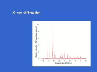
Mo Target impacted by electrons accelerated by a 35 kV potential K Characteristic radiation → due to energy transitions in the atom K White radiation Intensity 1.4 0.6 0.2 1.0 Wavelength ()
Incident X-rays SPECIMEN Heat Fluorescent X-rays Electrons Scattered X-rays Compton recoil Photoelectrons Coherent From bound charges Incoherent (Compton modified) From loosely bound charges Transmitted beam X-rays can also be refracted (refractive index slightly less than 1) and reflected (at very small angles)
Incoherent Scattering (Compton modified) From loosely bound charges • Here the particle picture of the electron & photon comes handy Electron knocked aside 2 No fixed phase relation between the incident and scattered wavesIncoherent does not contribute to diffraction (Darkens the background of the diffraction patterns)
Fluorescent X-rays Knocked out electronfrom inner shell Vacuum Energylevels Characteristic x-rays (Fluorescent X-rays) (10−16s later seems like scattering!) Nucleus
A beam of X-rays directed at a crystal interacts with the electrons of the atoms in the crystal • The electrons oscillate under the influence of the incoming X-Rays and become secondary sources of EM radiation • The secondary radiation is in all directions • The waves emitted by the electrons have the same frequency as the incoming X-rays coherent • The emission will undergo constructive or destructive interference Secondary emission Incoming X-rays
Sets Electron cloud into oscillation Sets nucleus into oscillation Small effect neglected
Oscillating charge re-radiates In phase with the incoming x-rays
BRAGG’s EQUATION Deviation = 2 Ray 1 Ray 2 d dSin • The path difference between ray 1 and ray 2 = 2d Sin • For constructive interference: n = 2d Sin
In plane scattering is in phase Incident and scattered waves are in phase if Scattering from across planes is in phase
Extra path traveled by incoming waves AY These can be in phase if and only if incident = scattered Extra path traveled by scattered waves XB But this is still reinforced scatteringand NOT reflection
Bragg’s equation is a negative law If Bragg’s eq. is NOT satisfied NO reflection can occur If Bragg’s eq. is satisfied reflection MAY occur • Diffraction = Reinforced Coherent Scattering Reflection versus Scattering X-rays can be reflected at very small angles of incidence
n = 2d Sin • n is an integer and is the order of the reflection • For Cu K radiation ( = 1.54 Å) and d110= 2.22 Å
In XRD nth order reflection from (h k l) is considered as 1st order reflectionfrom (nh nk nl)
Crystal structure determination Many s (orientations) Powder specimen POWDER METHOD Monochromatic X-rays Single LAUETECHNIQUE Panchromatic X-rays ROTATINGCRYSTALMETHOD Varied by rotation Monochromatic X-rays
Intensity of the Scattered electrons C B A Scattering by a crystal Electron Atom Unit cell (uc)
A Scattering by an Electron Emission in all directions Sets electron into oscillation Coherent(definite phase relationship) Scattered beams
For an polarized wave z P r For a wave oscillating in z direction x Intensity of the scattered beam due to an electron (I)
E is the measure of the amplitude of the wave E2 = Intensityc For an unpolarized wave IPy = Intensity at point P due to Ey IPz = Intensity at point P due to Ez
Scattered beam is not unpolarized Very small number • Rotational symmetry about x axis + mirror symmetry about yz plane • Forward and backward scattered intensity higher than at 90 • Scattered intensity minute fraction of the incident intensity Polarization factorComes into being as we used unpolarized beam
30 20 Schematic f→ 10 0.2 0.6 0.4 0.8 1.0 (Å−1)→ B Scattering by an Atom Scattering by an atom [Atomic number, (path difference suffered by scattering from each e−, )] • Angle of scattering leads to path differences • In the forward direction all scattered waves are in phase Scattering by an atom [Z, (, )]
C Scattering by the Unit cell (uc) • Coherent Scattering • Unit Cell (uc) representative of the crystal structure • Scattered waves from various atoms in the uc interfere to create the diffraction pattern The wave scattered from the middle plane is out of phase with the ones scattered from top and bottom planes
Ray 1 = R1 Ray 3 = R3 B A Unit Cell x S R Ray 2 = R2 B d(h00) a M N (h00) plane C
Independent of the shape of uc Extending to 3D Note: R1 is from corner atoms and R3 is from atoms in additional positions in uc
In complex notation • If atom B is different from atom A the amplitudes must be weighed by the respectiveatomic scattering factors (f) • The resultant amplitude of all the waves scattered by all the atoms in the uc gives the scattering factor for the unit cell • The unit cell scattering factor is called the Structure Factor (F) Scattering by an unit cell = f(position of the atoms, atomic scattering factors) Structure factor is independent of the shape and size of the unit cell
Structure factor calculations Simple Cubic A Atom at (0,0,0) and equivalent positions F is independent of the scattering plane (h k l)
B C- centred Orthorhombic Atom at (0,0,0) & (½, ½, 0) and equivalent positions Real (h + k) even Both even or both odd e.g. (001), (110), (112); (021), (022), (023) Mixture of odd and even (h + k) odd e.g. (100), (101), (102); (031), (032), (033) F is independent of the ‘l’ index
Body centred Orthorhombic C Atom at (0,0,0) & (½, ½, ½) and equivalent positions Real (h + k + l) even e.g. (110), (200), (211); (220), (022), (310) (h + k + l) odd e.g. (100), (001), (111); (210), (032), (133)
D Face Centred Cubic Atom at (0,0,0) & (½, ½, 0) and equivalent positions (½, ½, 0), (½, 0, ½), (0, ½, ½) Real (h, k, l) unmixed e.g. (111), (200), (220), (333), (420) (h, k, l) mixed e.g. (100), (211); (210), (032), (033) Two odd and one even (e.g. 112); two even and one odd (e.g. 122)
E Na+ at (0,0,0) + Face Centering Translations (½, ½, 0), (½, 0, ½), (0, ½, ½)Cl− at (½, 0, 0) + FCT (0, ½, 0), (0, 0, ½), (½, ½, ½) NaCl: Face Centred Cubic
Zero for mixed indices (h, k, l) mixed e.g. (100), (211); (210), (032), (033) (h, k, l) unmixed If (h + k + l) is even If (h + k + l) is odd Presence of additional atoms/ions/molecules in the uc (as a part of the motif ) can alter the intensities of some of the reflections
Relative Intensity of diffraction lines in a powder pattern Structure Factor (F) Scattering from uc Multiplicity factor (p) Number of equivalent scattering planes Polarization factor Effect of wave polarization Lorentz factor Combination of 3 geometric factors Absorption factor Specimen absorption Temperature factor Thermal diffuse scattering
Lorentz factor Polarization factor
Intensity of powder pattern lines (ignoring Temperature & Absorption factors) • Valid for Debye-Scherrer geometry • I → Relative Integrated“Intensity” • F → Structure factor • p → Multiplicity factor • POINTS • As one is interested in relative (integrated) intensities of the lines constant factors are omitted Volume of specimen me , e (1/dectector radius) • Random orientation of crystals in a with Texture intensities are modified • Iis really diffracted energy (as Intensity is Energy/area/time) • Ignoring Temperature & Absorption factors valid for lines close-by in pattern
Crystal = Lattice + Motif • In crystals based on a particular lattice the intensities of particular reflections are modified they may even go missing Diffraction Pattern Position of the Lattice points LATTICE Intensity of the diffraction spots MOTIF
Reciprocal Lattice Properties are reciprocal to the crystal lattice The reciprocal lattice is created by interplanar spacings
A reciprocal lattice vector is to the corresponding real lattice plane • The length of a reciprocal lattice vector is the reciprocal of the spacing of the corresponding real lattice plane • Planes in the crystal become lattice points in the reciprocal lattice ALTERNATE CONSTRUCTION OF THE REAL LATTICE • Reciprocal lattice point represents the orientation and spacing of a set of planes
Reciprocal Lattice The reciprocal lattice has an origin!
Reciprocal lattice is the reciprocal of a primitivelattice and is purely geometrical does not deal with the intensities of the points Physics comes in from the following: • For non-primitive cells ( lattices with additional points) and for crystals decorated with motifs ( crystal = lattice + motif) the Reciprocal lattice points have to be weighed in with the corresponding scattering power (|Fhkl|2) Some of the Reciprocal lattice points go missing (or may be scaled up or down in intensity) Making of Reciprocal Crystal (Reciprocal lattice decorated with a motif of scattering power) • The Ewald sphere construction further can select those points which are actually observed in a diffraction experiment
Examples of 3D Reciprocal Lattices weighed in with scattering power (|F|2) SC 001 011 101 111 Lattice = SC 000 010 100 110 No missing reflections Reciprocal Lattice = SC Figures NOT to Scale