Download
1 / 1
10 likes | 105 Vues
Explore sensitivity studies for the LCLS Photoinjector beamline, focusing on alignment, laser quality, and emittance deterioration to improve performance. Results project reduced emittance levels and nominal tuning in simulations.

E N D
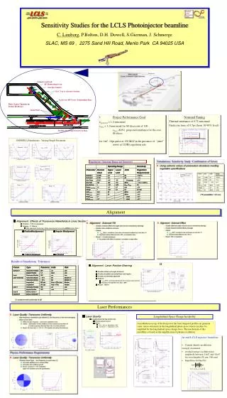
th = 0.72 mm.mrad th = 0.36 mm.mrad Preinjector: ± Solenoid 1 0.3% f ± ° ± 2.5 E 0.5% gun gun Linac Field 12 % Solenoid 2 20% ( E = 150 MeV ) Final Position Position Misalignement Misalignment Angular Misalignment Angular Misalignment Position Position Misalignement Misalignement Angular Misalignment Angular Misalignment At end beamline At end beamline ~2% increase level ~2% increase level ± ± m m ± ± m m 0.12 0.12 mrad mrad 150 150 m maximum m maximum 0.12 0.12 mrad mrad 150 150 m maximum m maximum Laser Quality Laser Quality Laser Quality Longitudinal Flat top Uniformity Longitudinal Flat top Flatness Longitudinal Flat top Flatness Emittance deterioration Emittance deterioration Emittance deterioration Result : Result : Result : l m l m For > 240 , Modulation < 20% m For > 240 , Modulation < 20% m l m For > 240 , Modulation < 20% m m l m l For 240 < , Modulation < 30% m For 240 < , Modulation < 30% m m l For 240 < , Modulation < 30% m 5% level 5% level 20% peak - to - peak Sensitivity Studies for the LCLS Photoinjector beamline C. Limborg, P.Bolton, D.H. Dowell, S.Gierman, J. Schmerge SLAC, MS 69 , 2275 Sand Hill Road, Menlo Park CA 94025 USA • Project Performance Goal projected < 1.2 mm.mrad slice < 1.0 mm.mrad for 80 slices out of 100 slice(80%) projected emittance for the core 80 slices for 1nC, 10ps pulse at 150 MeV,in the presence of “jitter” errors at 120Hz repetition rate Nominal Tuning Thermal emittance of 0.72 mm.mrad Finite rise time of 0.7ps (from 10-90% level) PARMELA Simulations : Varying Single Parameter Alignment Alignment : Effects of Transverse Wakefields in Linac Sections Effects of : Effects of Wakefields : ± m ± m Position : 150 m maximum Position : 150 m maximum ± m Position : 150 m maximum Angular : 0.12 mrad Angular : 0.12 mrad Angular : 0.12 mrad m m With alignment & steering : those requirements are easily met (B PM resolution 20 m ) With alignment & steering : those requirements are easily met (B PM resolution 20 m ) m With alignment & steering : those requirements are easily met (B PM resolution 20 m ) Alignment : Laser Position Steering Alignment : Laser Position Steering Alignment : Laser Position Steering Creates offset and angle of bunch Creates offset and angle of bunch Creates offset and angle of bunch Creates head - tail centroids offsets and angles Creates head - tail centroids offsets and angles Creates head - tail centroids offsets and angles Creates slice emittance growth Creates slice emittance growth Creates slice emittance growth Criteria: Criteria: Criteria: ge ge (80%) at entrance Linac not increase by more than 5% (80%) at entrance Linac not increase by more than 5% ge (80%) at entrance Linac not increase by more than 5% slice slice slice m m Head - tail centroid offset less than 100 m Head - tail centroid offset less than 100 m m Head - tail centroid offset less than 100 m m m Result : 100 m Result : 100 m m Result : 100 m Laser Performances Longitudinal Space Charge Instability A modulation on top of the flat part of the laser temporal profile can generate some micro-structures in the longitudinal phase space which can then be amplified by the longitudinal space charge force. The mechanism of this instability is based on the amplification of plasma oscillation.