Hydronic Heating
Hydronic Heating. North Seattle Community College HVAC Program Instructor – Mark T. Weber, M.Ed. Hydronic - 1. Introduction to Hydronic Heating. There are two types of hydronic heat: High temp and low temp Water or steam carries heat through a piping arrangement to the areas being heated


Hydronic Heating
E N D
Presentation Transcript
Hydronic Heating North Seattle Community College HVAC Program Instructor – Mark T. Weber, M.Ed. Hydronic - 1
Introduction to Hydronic Heating • There are two types of hydronic heat: High temp and low temp • Water or steam carries heat through a piping arrangement to the areas being heated • Terminal units are located in the heated spaces • Systems can be designed to handle multiple zones • Water is heated at the boiler (gas, oil, or electric)
Introduction to Hydronic Heating (cont'd.) • Boiler cycles on and off to maintain temperature • Water is circulated through the system with pumps A four-zone hydronic heating system.
The Heat Source • Boiler: appliance that heats water using oil, gas, or electricity as a heat source • Some boilers can use more than one source • Can supply water at various temperatures, but most common is 180°F or 120 F • Cast-iron boilers are the most commonly found in residential applications • Steel boiler: water being heated surrounds steel tubes carrying combustion gases
The Heat Source (cont'd.) • Copper water-tube boiler: low mass boiler, smaller and with lower capacity than cast-iron or steel but efficient • The geothermal heat pump transfers heat from the earth to a water/water-antifreeze mixture and can heat water to 130°F
The Basic Hydronic System • Expansion tank • Water expands when heated, so expansion tanks accommodate added volume to prevent excess pressure • Standard expansion tank is a large tank located above the boiler • Diaphragm-type expansion tanks have two sections separated by a semi-permeable rubber membrane • One side contains pressurized air; other is open to water circuit
The Basic Hydronic System (cont'd.) Cutaway of a diaphragm-type expansion tank. Photo by Eugene Silberstein Expansion tank data tag. Photo by Eugene Silberstein
The Basic Hydronic System (cont'd.) • Circulator/centrifugal pumps • Force hot water from heat source through piping to heat transfer units and back to the boiler using centrifugal force • Made up of a motor, a linkage, and an impeller When the impeller is rotated, it “throws” the water away from the center of the pump and out through the opening.
The Point of No Pressure Change • Point in the system where the pressure, no matter what the system is doing, remains the same • Provides a reference point for system evaluation and a location for multiple system-component connections • Desired connection point for inlet of the circulator pump, inlet of the expansion tank, air separator, air vent, and outlet of the pressure-reducing (water-regulating) valve
Other Hydronic System Components • Air separator and air scoop • Air is one of the biggest enemies of a hot water hydronic heating system • Air separator separates air from water using collision and adhesion • Directional air scoops separate and remove air on horizontal stretches of pipe
Other Hydronic System Components • Air vent removes air from system • Can be manually operated or automatic • Temperature-limiting control (aquastat) maintains water temperature in system
Other Hydronic System Components (cont'd.) Wire screen in the air separator.
Other Hydronic System Components (cont'd.) • High-limit control shuts own the heat source if boiler water gets too hot • Water-regulating valve (pressure-reducing valve) reduces pressure of water entering the boiler to desired level • Pressure relief valve discharges excess water when expansion creates pressure • Set to relieve at or below maximum working pressure of the low-pressure boiler (30 psig)
Other Hydronic System Components (cont'd.) A low-water cut-off.
Other Hydronic System Components (cont'd.) • Low-water cut-off deenergizes system if level of water in system drops below desired level • Zone valves are thermostatically controlled valves that control water flow to the various zones in the system • May be gear-motor or heat-motor operated, and can often be opened manually • Available in two-port and three-port varieties
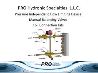
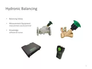
Other Hydronic System Components (cont'd.) • Balancing valves ensure resistance to water flow is the same in all flow paths • Resistance of water flowing in system causes friction • Valves are installed in each circuit branch • Pressure differential bypass valve relieves noise and pressure from closing multiple zone valves in two-port systems • Opens incrementally as valves close
Other Hydronic System Components (cont'd.) • Flow control valve prevents water from flowing through wrong heating loop (ghost flow) • Outdoor reset control senses outdoor ambient temperature and adjusts the water temperature in the boiler • Thermostatic radiator valves are a common method for controlling temperature in each of multiple zones
Other Hydronic System Components (cont'd.) • Finned-tube baseboard units are common terminal heating units • Heated water flows through piping, transferring heat to fins • Air passes over hot fins and rises by convection • Sections are rated in Btu per linear foot (Btuh/ft), determined by temperature and water flow rate
High-Temperature Hydronic Piping Systems • Consist of previously discussed components connected together • The series loop system • Most common hydronic system because of low installation costs • Like a series electric circuit, terminal units are piped so outlet of one heat emitter is inlet of next • Main drawback is that individual temperature control for each area being heated is impossible and each terminal unit is cooler than last
High-Temperature Hydronic Piping Systems (cont'd.) • One-pipe system • One main piping loop extends around the occupied space and connects outlet of boiler back to boiler return • Each terminal unit connects to main loop with two tees, which may be designed for use on a one-pipe system • Proper operation relies on proper ratios of resistance between terminal unit branch and resistance to flow in pipe between the tees
High-Temperature Hydronic Piping Systems (cont'd.) • Factors to consider in laying out, evaluating, or installing a one-pipe system: • Length of the terminal branch circuit, distance between the tees, size of piping in branch circuit and between the tees, and location of the terminal unit with respect to the main loop • Diverter or Monoflo tees are special tees for one-pipe systems, designed to increase resistance in the main loop pipe section between the two tees so that more water will be directed through the terminal heating units
High-Temperature Hydronic Piping Systems (cont'd.) • The two-pipe direct-return system • Uses one pipe to carry water to the terminal units and another to carry water from the terminal units back to the boiler • Terminal unit closest to the boiler will have the shortest piping run (lowest resistance) while the unit farthest from the boiler will have the longest
High-Temperature Hydronic Piping Systems (cont'd.) • The two-pipe reverse-return system • First terminal unit to be supplied with water is the last to return water to the boiler • Unit with shortest supply pipe will have longest return pipe and vice versa
High-Temperature Hydronic Piping Systems (cont'd.) • Primary-secondary pumping • Involves at least two separate piping circuits between the boiler and terminal unit circuits • One circuit path flows from the boiler supply back to the boiler return • The secondary circuit(s) is/are connected to the main/primary circuit and share a portion of piping • Uses standard tees • Mixing valves combine two water streams of different temperatures
High-Temperature Hydronic Piping Systems (cont'd.) • One of many benefits of primary-secondary pumping is that each loop can be used to supply water at different temperatures to the terminal units in that loop • Primary-secondary systems do not have expansion tanks in each of the secondary loops because the common piping between the primary and secondary loops serves as the expansion tank for that loop
Radiant, Low Temperature Hydronic Piping Systems • Rely on heating the shell of the structure as opposed to the air in that structure • The human body acts as a radiator • Under normal conditions, the body produces about 500 Btu/h but only requires 100 Btu/h to remain alive; typically a room temperature of 68°F allows us to shed the extra 400 Btu/h comfortably • The area close to the ceiling can be cooler and the floor should be warmer
Radiant, Low Temperature Hydronic Piping Systems (cont'd.) • Main differences between radiant heating and conventional hydronic systems: • Radiant heating systems are nearly invisible compared to conventional hydronic systems • Different piping materials • Radiant systems often use polyethylene (PEX) tubing instead of copper piping • Water temperature in radiant heating systems considerably lower than in conventional hydronic systems (avg. of 120°F)
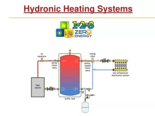
Radiant, Low Temperature Hydronic Piping Systems (cont'd.) • Heat sources for radiant heating systems • Geothermal heat pump system • Use a buffer tank • Copper-tube, low-mass boiler • A buffer tank is still a good idea • Direct piping • Boiler must be designed to handle potentially low temperature of water returning to the tank or provide a means to keep return-water temperature high enough to prevent flue-gas condensation
Radiant, Low Temperature Hydronic Piping Systems (cont'd.) • Radiant heat piping applications • Slab on grade • Popular for new construction applications • Spacing of PEX tubes in fresh concrete depends on depth below concrete surface, size of tubes, type of floor, and location of tubes with respect to the outside walls of the structure • Place insulation and a vapor barrier below the concrete slab to prevent losing heat to ground
Radiant, Low Temperature Hydronic Piping Systems (cont'd.) • Thin slab • Common when there is an existing floor in place • 1.5-2” slab of concrete poured over tubing; completely cover PEX tubing with at least ¾” of concrete • Dry applications • Staple the tubing to the bottom of the flooring material (staple-up job) • Keep staples closely spaced so that tubing is in loose contact with floor for effective heat transfer
Radiant, Low Temperature Hydronic Piping Systems (cont'd.) • Many different piping arrangements can be used with radiant heating, including: • Direct piping is the simplest configuration • Best to use a buffer tank with a boiler • Manually set mixing valves do not respond to changes in water temperature or flow rate • Thermostatic mixing valves adjust internal settings to supply water at the desired temperature; prevents flue gas condensation
Combination (High- and Low-Temperature) Piping Systems • In the case where a structure has both high and low temperature heating circuits, the same boiler can be used to serve both applications using a primary-secondary pumping arrangement
Tankless Domestic Hot Water Heaters • Most oil and gas fired hot water heating boilers can be furnished with a domestic hot water heater consisting of a coil inserted into the boiler containing the domestic hot water, heating it quickly • Eliminates the need for a storage tank • An efficient way to produce hot water
For more information please contact Mark T. Weber At North Seattle Community College WWW.NorthSeattle.edu Mark.weber@seattlecolleges.edu