Magnetic Forces
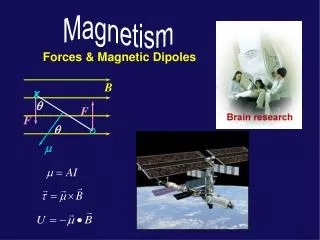
Magnetic Forces. Lorentz Force The force exerted by the magnetic flux density B on a single charge q : The force is at right angles to u and B The magnitude is q u B sin q The magnetic force does no work The total force is given by. This force is called the Lorentz force!.

Magnetic Forces
E N D
Presentation Transcript
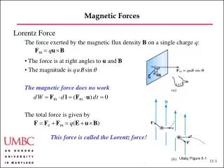
Magnetic Forces • Lorentz ForceThe force exerted by the magnetic flux density B on a single charge q: • The force is at right angles to u and B • The magnitude is quBsinq • The magnetic force does no work • The total force is given by This force is called the Lorentz force! Ulaby Figure 5-1
Magnetic Forces • Comparison of Electric and Magnetic Forces
Magnetic Forces y x Example: Uniform Motion in a Magnetic Field Question: A charge is moving in a uniform magnetic field . Show that the charges move in a spiral Answer: The equations of motion are u B
Magnetic Forces y x Example: Uniform Motion in a Magnetic Field Answer (continued): After further integration, we find which is indeed a spiral. This motion is called cyclotron motion. The rotation frequency is independent of the velocity! By accelerating the charges, using a periodically-varying electric field, it is possible to obtain very high energies. u B
Magnetic Forces • Current-Carrying Wire • A current I flowing in a wire segment of length dl experiences a force • In (a), there is no force • In (b), the force is to the left • In (c), the force is to the right • Over a closed loop, we have • The force on a closed loop in a constant magnetic field is zero Ulaby Figure 5-2
Magnetic Forces Magnetic Torque A force F exerted on a moment arm d exerts a torque T, T = d × F Electric motors operate using the torques exerted by magnetic fields Magnetic field in the plane of a current loop: Arms 1 and 3 of the loop experience forces The resulting torque is (A = area of loop) Ulaby Figure 5-6
Magnetic Forces • Magnetic Torque • More generally, • where is the surface normal — using the right-hand rule • With N turns, this expression becomes • m = the magnetic moment • Since current flows in loops, the magnetic moment is a fundamental quantity — analogous to electric dipoles Ulaby Figure 5-7
Biot-Savart Law • Magnetic analogue to Coulomb’s law • Since magnetic field are generated by currents, it is bit more complicated… • NOTE: There is no such thing as a “point current” • — The Biot-Savart law only exists in continuous form • Surface and Volume Distributions Ulaby Figure 5-8
Magnetic Fields and Forces Magnetic Field of a Linear Conductor: Ulaby Example 4-2 Question: A linear conductor of length l and carrying a current I is placed along the z-axis. What is the magnetic flux density B at a point Pat a distance r in the x-y plane in free space? Answer: We have andso that with Ulaby Figure 5-10
Magetic Fields and Forces Magnetic Field of a Linear Conductor: Ulaby Example 4-2 Answer (continued): We conclude When NOTE: From the result for segments of length l, we can build up arbitrary curves. Ulaby 2001 Ulaby Figure 5-10
Magnetic Fields and Forces Magnetic Field of a Circular Loop: Ulaby Example 4-4 Question: A circular loop of radius a on the x-y plane is carrying a current I. Determine the magnetic field H along the z-axis. Answer: A current segment dl creates amagnetic field in both the z- and r-directions. Thez-components add, while the r-components cancel. We have Ulaby Figure 5-12
Magnetic Fields and Forces Magnetic Field of a Circular Loop: Ulaby Example 4-4 Answer (continued): Integrating over the loop, we obtain When z is large, this becomes: where m is the magnetic moment Ulaby Figure 5-12
Magnetic Fields and Forces • Magnetic Dipole Field: • More generally, we have far away from a current loop at P(R, q, f ) • This expression is analogous to what we found for the electric dipole. • Near to the dipole, the fields do not look the same. Ulaby 2001 Ulaby Figure 5-13
Magnetic Fields and Forces • Force between two conductors • Since conductors create fields, one conductor will exert a force on another • — The field B1 due to the current I1 at the location of current I2 is given by • so that the force on a wire of length l is • and the force per unit length is From Newton’s second law, theforce exerted by wire 2 on wire 1 mustbe equal and opposite! Ulaby Figure 5-14
Integral Form of Magnetostatic Equations • Gauss’s Law for Magnetism • There is no magnetic charge • Magnetic field lines always form continuous closed loops • You cannot have an isolated north pole or south pole in a magnet — The flux entering a region surrounding a charge in an electric dipole is non-zerio — The flux entering a region surrounding a pole in a magnetic dipole (bar magnet) is zero. Ulaby Figure 5-15
Integral Form of Magnetostatic Equations • Ampere’s Law • C is any closed contour • I is the current flowing through any surface that is attached to C • Why emphasize any? • In three dimensions: • — The volume surrounded by a closed surface S is unambiguous • — The surface S attached to a closed contour C is ambiguous(There are many of them)
Integral Form of Magnetostatic Equations I1 C S2 I2 • Ampere’s Law • C is any closed contour • I is the current flowing through any surface that is attached to C • Some consequences: • Current cannot be created or destroyed (I1 = I2) • The sum of the currents flowing into any closed surface is zero … which in turn implies: • Kirchhoff’s Current Law: The sum of the currents flowing into any node is zero. • — To prove the theorem, you surround node by an arbitrary closed surface. S1
Ampere’s Law • In situations with high symmetry, one can calculate the field • current line • current sheet • torus • This is analogous to using Gauss’s law in electrostatics, but there is no magnetic charge • Again, as in the case of electrostatics: • An even more important application of the integral formulation in today’s world is to serve as the starting point for numerical approaches!
Tech Brief 10: Electromagnets • First developed by William Sturgeon in 1820s • Basic Principle • Can be constructed in many shapes • linear solenoid • horseshoe • Electric current flows through insulated wire coiled around a core • Produces magnetic field with bar magnet-like field • Field strength proportional to • Current • Number of turns • Permeability of core • Field strength increased by ferromagnetic core
Tech Brief 10: Electromagnets • Applications • Motors • Relays • Loud speakers • Magnetic levitation • Many others • Doorbell • Electromagnet pulls on a metal bar anchored on one side (contact arm). Pulling on the bar severs current flow, so the arms snaps back, restoring current. This happens many times per second, and on each cycle, the clapper arm, attached to the contact arm hits a bell. • Magnetic Relays • A circuit breaker switched • electromagnetically
Tech Brief 10: Electromagnets Loudspeaker Uses a combination of stationary permanent magnet and a movable electromagnet. Cone attached to electromagnet moves in response to electrical signal. Cone movement creates sound waves with same spectral content as electrical signal Magnetic Levitation Maglev trains achieve speeds as high as 500 km/hr because there is no friction between the train and the track. The train carries superconducting electromagnets that induce currents in coils built into the guide rails alongside the train. The magnetic interaction both levitates and propels the train along the track.
Vector Potential • In electrostatics, we have • In magnetostatics, we have • The constraint is automatically satisfied since for any vector C. • The vector potential — because it is a vector — is less useful than the scalar potential for doing calculations.
Boundary Conditions • Normal boundary conditions: • In electrostatics: • In magnetostatics: field decomposition intotangential and normal components tangential boundary conditions normal boundary conditions Ulaby Figure 5-24
Boundary Conditions • Tangential boundary conditions: • In electrostatics: • In magnetostatics: field decomposition intotangential and normal components tangential boundary conditions normal boundary conditions Ulaby Figure 5-24
Boundary Conditions Summary of electric and magnetic boundary conditions
Inductance Solenoids Inductors typically use solenoids that have many circular loops; using many loops increases the inductance. When tightly wound — the usual case — the field resembles the field of a bar magnet Solenoid parameters: N = total number of turns l = total length n = turns per unit length = N / l a = solenoid radius I = current Ulaby Figure 5-25
Inductance • Solenoids • We recall that the field on the z-axis of a loop is • An incremental length dz has ndz turnsand a current • Its contribution to the flux density is • Integrating, we obtain • which for a long solenoid becomes • In this context, “long” means [See slide 11.11] Ulaby Figure 5-26
Inductance • Self-Inductance (= The usual inductance) • We define the magnetic flux “linking” (passing through) a surface as • In a solenoid, which has an approximately constant magnetic field, • The magnetic flux linkage L in an N-loopstructure is defined as Ulaby Figure 5-26
Inductance • The inductance is defined as • Coaxial cable • Hence, the flux through S is • We conclude Note: This result is general! Ulaby Figure 5-27
Magnetic Energy • From circuit theory • The voltage across an inductor: v = LdI/dt • The power expended: p = IV • The energy stored is thus: • Applying this expression to a solenoid • More generally, • where is the energy density volume
Applications (Paul) High-Voltage Transmission Lines: Health Issues High-voltage transmission lines carry three-phase voltages. The voltagebetween lines is typically VLL = 765 kV. What is the voltage at a man’s head, standing below? We have so that Paul Figure 3-49
Applications (Paul) • High-Voltage Transmission Lines: Health Issues • The fields are all 120o out of phase, so that • This is strong enough to make a fluorescent light bulb glow! • A similar calculation shows that B = 21.4 m T = half earth’s field at surface • What are the health risks? Is there a resonance in the brain at 60 Hz? • Studies are ambiguous… • You should avoid exposure tolarge fields! Paul Figure 3-49
Applications (Paul) • Electrostatic Discharge • Voltages of about 3 kV can lead to electrostatic discharge (air breakdown)— This can be a serious problem with computer equipment • Poor conductors (good dielectrics) accumulate charge — including dry human skin; hence we ground our hands when working sensitive equipment • Some materials give up electrons easily: air, human skinSome materials accept electrons easily: teflon, silicon • A rough estimate: The capacitance of sphere of radius a is C = 4pe0 a. Taking a for the human body as 1 m, we find C = 100 pF. With only 1 mCon the body, we find V = 10 kV. That is enough to cause discharges!
Applications (Paul) • Interference • Video displays and power wires are a major source of interference • Traditional video displays work by boiling electrons off a cathode, accelerating them in an electric field, deflecting them in a magnetic field, and having them hit a phosphorescent material on the anode. • Magnetic fields can be quite large relative to the Earth’s field (50 mT)Using: • with a = 5 cm, d = 10 cm,I = 0.6 A, and N = 1000,we find B = 700 mT • This must be properly shielded! Paul Figure 3-51
Applications (Paul) • Parasitic Effects • Since charges and currents are linked, you cannot have capacitance without inductance — and vice versa! • The inductance and capacitance of two well-separated wires of length l are • where s = wire separation, a = wire radii • As leads to another capacitor, they createa parasitic inductance and the equivalentcircuit shown • Example: l = 0.5 in, s = 0.25 in, a = 16 mils,C = 1000 pF. We find Llead = 14 nH and • Clead = 0.1 pF (negligible) • We have f0 = 40 MHz • Above this frequency, the capacitor becomes an inductor Paul Figure 3-53
Applications (Paul) • Electrostatic Shielding • Inside a conducting surface (Faraday cage),the voltage is fixed and the field is zero. • The bodies of airplanes and cars makedecent Faraday cages. Paul Figure 3-55 Paul Figure 3-54
Applications (Paul) • Electric Generator • When wires turn, positive and negative chargesexperience opposite forces, leading to currentflow and an effective EMF = electromotive force • where w = rotation frequencyu = ww/2 = rotation velocity • A = wl = area enclosed by current loop • This is how electrical generators work! Mechanical energy is converted intoelectrical energy Paul Figure 3-57
Applications (Paul) • Electric Motor • We have already shown that the torque T is given by • Allowing B to vary periodically, • we can make the wires turn in one direction • This is how electrical motors work! Electrical energy is converted intomechanical energy Paul Figure 3-58
Tech Brief 11: Inductive Sensors • Basic principle: magnetic coupling between different coils • Applications • Position/displacement measurement • Proximity detection • Other related applications • Linear Variable Differential Transformer (LVDT) • Primary core connected to AC source (1-10 kHz typical) • Pair of secondary coils • All coils share a common ferromagnetic core • Secondary coils are connected in opposition, so when core is in center, there is zero output • When core is not in center, output voltage is nonzero, indicating position of core • Core attached to outside by a nonmagnetic rod • Approximately linear relationship between output voltage amplitude and displacement over a wide range
Tech Brief 11: Inductive Sensors • Eddy Current Proximity Sensor • Sensitive indicator of a conductor • When an object is in front of the secondary coil, the magnetic field of the coil produces eddy (circular currents in the object. • Eddy currents generate magnetic fields of their own opposing the field in the coil. • Reduction in flux in coil decreases output voltage • Magnitude of voltage change depends on object’s conductive properties and distance from sensor
Assignment • Reading: Ulaby, Chapter 6 • Problem Set 5: Some notes. • There are 7 problems. As always, YOU MUST SHOW YOUR WORK TO GET FULL CREDIT! • Please watch significant digits. • Get started early!