Download
1 / 18
230 likes | 517 Vues
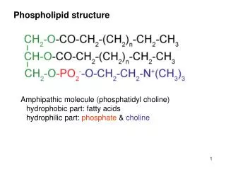
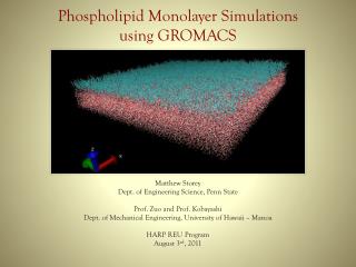
Phospholipid Monolayer Simulations using GROMACS. Matthew Storey Dept. of Engineering Science, Penn State Prof. Zuo and Prof. Kobayashi Dept. of Mechanical Engineering, University of Hawaii – Manoa HARP REU Program August 3 rd , 2011. Overview of Presentation.

E N D
Phospholipid Monolayer Simulations using GROMACS Matthew Storey Dept. of Engineering Science, Penn State Prof. Zuo and Prof. Kobayashi Dept. of Mechanical Engineering, University of Hawaii – Manoa HARP REU Program August 3rd, 2011
Overview of Presentation • Introduction to Prof. Zuo’s research • GROMACS introduction and general simulation methodology • Specific steps to simulate DPPC monolayer • Results of energy minimization and equilibrium parameter optimization • Major errors/problems encountered • Conclusion and recommended future work
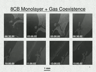
One focus of Prof. Zuo’s research is the characterization of lung surfactants. Experimental AFM images of lung surfactants during lateral compression [2]
GROMACS and VMD were used this summer to set up and run MD simulations of DPPC monolayers. GROMACS • is a free publically licensed software for protein and lipid simulations • Fast calculations for non-bonded interactions • capable of being run in parallel with MPI VMD • (Visual molecular dynamics) is a free publication-quality MD structure and trajectory viewer • no limit on number of atoms in system
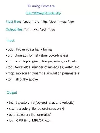
The majority of MD simulations in GROMACS follow the same general approach. • Select property of interest and appropriate force fields • Generate the raw initial layout of your system (file.gro) • Make a coordinate file (file.top) forming the connection between force field parameters and system structure • Generate box size for simulation, add solvent, and counter ions (if needed).
General approach continued 5. Run energy minimization on solvated system • Determine run parameters for equilibrium simulations • First NVT is run to equilibrate temperature • Then run NPT to relax to density required for simulation 7. Select appropriate simulation parameters for the Production simulation 8. Analyze/Visualize the resulting data to get property of interest
The first step in my simulation was to determine the more appropriate force field: Coarse or Fine Grain. • FG more detailed, but computationally expensive time step (2 fs) • CG is faster (4:1 atom mapping) large time steps (20-40 fs) • Monolayer conformations and surface pressure readings require long equilibration times, so CG model was chosen • MARTINI force field is free and most widely used CG field for GROMACS simulations [13]
Both the Coarse and Fine Grain simulation systems were built using the following procedure. 5. Randomly generate large sample size 2. Remove all solvent and top half of equilibrated bilayer 1. Start with pre-equilibrated DPPC bilayer from MARTINI 4. Remove solvent above monolayer 3. Solvate entire system
Simulation parameters were then determined for the minimization and equilibration steps. • Need large scale sample (+1000 DPPC) • Large CG time step = 30 fs • Constant temperature above or below 314 K Temp = 300 K • Semi isotropic pressure coupling with 1atm normal pressure • Simulation time: 100ns- 1us for equilibration Poor PBC setup from literature Periodic Boundary Conditions x/y PBC with 2 walls Walls – 9-3 LJ potential with a density of 110 nm-3 /nm-2 [1]
The first results were a performance study between the constructed CG and FG monolayer systems. CG model FG model dt = 40fs dt = 2fs 96,650 atoms 431,900 atoms Performance at 120 processors ~ 1200 ns/day ~9 ns/day
During the energy minimization step, a density study was performed to determine the optimal wall density.
After the EM procedure, the time step and wall density were examined together during the NVT equilibration. The 110 density had the most stable potential curve and as expected didn’t blow up for the stable time steps Since 30 fs is the largest stable time step at the optimal wall density, it was chosen for the equilibrium simulations
The first major error of this project occurred immediately after installing GROMACS on HOSC. • Mhpcc help desk said only thing I needed in my path was correct compilers for GROMACS • After a week of email exchanges with help desk 2 compilers were found in path • OpenFOAM third party compiler found in path; got rid of OpenFOAM source in .bashrc and solved problem (since I never use it).
After deciding to simulate with the CG model, realistic solvation of the system became a problem. • Since MARTINI atoms are approximate shells, VDW radii were inaccurate in the solvation executable • Adjusted vdw radii (trial and error) until looked right • Compared to FG model of same size to see if water level was too high in CG model
The most recent problem occurred during the NVT simulation when the system kept blowing up. • Density too high in walls defined at the top and bottom of system • Time step too large and energies not updated frequently enough • Ran density and time step study to find fastest, most stable case, which had a density of 110 nm-3/nm-2 and a time step of 30 fs
Conclusion / Recommended future work • While there were some problems during the project, an overall understanding of GROMACS and a foundation for simulating lipid monolayers were accomplished • Future work can be done on generating detailed isotherms for pure DPPC monolayers • Afterwards, slight adjustments can be made to the composition of this DPPC monolayer to create other surfactant models, which can be simulated and analyzed in a similar fashion
Acknowledgements I would like to thank the following: • Prof. Zuo and Prof. Kobayashi • Dr. Brown • Sheree Hashimoto "This material is based upon work supported by the National Science Foundation under Grant No. 0852082. Any opinions, findings, and conclusions or recommendations expressed in this material are those of the author(s) and do not necessarily reflect the views of the National Science Foundation."
References [1] Baoukina, S., Monticelli, L., Risselada, H., Marrink, S., & Tieleman, D. (2008). The molecular mechanism of lipid monolayer collapse. The National Academy of Sciences, 105(31), 10803-10808. [2] Zhang, H., Fan, Q., Wang, Y., Neal, C., & Zuo, Y. (2011). Comparative study of clinical pulmonary surfactants using atomic force microscopy. Biochimica Et Biophysica Acta, 1808, 1832-1842. [3] Duncan, S., & Larson, R. (2008). Comparing Experimental and Simulated Pressure-Area Isotherms for DPPC. The Biophysical Society, 1, 1-46. [4] Wong-Ekkabut, J., Baoukina, S., Triampo, W., Tang, I., Tieleman, D., & Monticelli, L. (2008). Computer simulation study of fullerene translocation through lipid membranes. Nature Publishing Group, 3, 363-368. [8] Scott, H. (2002). Modeling the lipid component of membranes. Current Opinion in Structural Biology, 12, 495-502. [10] Schneemilch, M. and Quirke, N. (2010). Molecular dynamics of nanoparticle translocation at lipid interfaces. Molecular Simulation, 36(11), 831 — 835. [11] Engin, O., Villa, A., Sayar, M., & Hess, B. (2010). Driving Forces for Adsorption of Amphiphilic Peptides to the Air-Water Interface. Journal of Physical Chemistry, 114, 11093–11101. [13] http://md.chem.rug.nl/cgmartini/index.php/about