Download
1 / 32
320 likes | 575 Vues
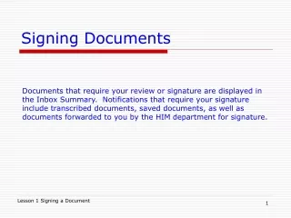
Signing Plan Design - At Grade Intersections TEM Chapter 6-4.0 General Principles of Traffic Signing. General Principles of Traffic Signing. 6-4.01 Basic Requirements for the Installation of Traffic Signs

E N D
Signing Plan Design -At Grade IntersectionsTEM Chapter 6-4.0General Principles of Traffic Signing
General Principles of Traffic Signing • 6-4.01 Basic Requirements for the Installation of Traffic Signs • As stated in the MN MUTCD, in order for traffic signs to be effective, they should meet the following basic requirements: • Fulfill a need. • Command attention. • Convey a clear, simple meaning. • Command respect of road users. • Give adequate time for proper response. Signing Plan Design (At-Grade) Manual
General Principles of Traffic Signing • 6-4.02 Basic Considerations for the Installation of Traffic Signs • As stated in the MN MUTCD, in order for traffic signs to be effective, they should meet the following basic requirements: • Design • size, color, shape • Placement • 20 degree cone of vision • Operation • Maintenance • UNIFORMITY Signing Plan Design (At-Grade) Manual
General Principles of Traffic Signing • 6-4.03 Functional Classifications of Traffic Signs • The MN MUTCD classifies signs by their functional usage as follows: • Regulatory signs inform highway users of traffic laws or regulations and indicate the applicability of legal requirements that would not otherwise be apparent. Signing Plan Design (At-Grade) Manual
General Principles of Traffic Signing • 6-4.03 Functional Classifications of Traffic Signs • Warning signs are used to call attention to hazardous conditions, actual or potential, on or adjacent to a highway or street, that would not be readily apparent to the motorist. Signing Plan Design (At-Grade) Manual
General Principles of Traffic Signing • 6-4.03 Functional Classifications of Traffic Signs • Guide signs are used to provide directions to motorists, informing them of intersecting routes, directing them to cities and other important destinations, and guiding them to available services, points of interest, and other geographic, recreational, or cultural sites. Signing Plan Design (At-Grade) Manual
General Principles of Traffic Signing • 6-4.03 Functional Classifications of Traffic Signs • 2001 ITE Traffic Control Devices Handbook Chapter 5 • Regulatory Signs (location specific) • Warning Signs • Regulatory Signs (nonlocation specific) • Guide Signs • Motorist Services • Traffic generator signs • General information signs Signing Plan Design (At-Grade) Manual
General Principles of Traffic Signing • 6-4.04 Department Classification by Sign Design Type • While the previous sign classifications describe general functions, Mn/DOT has further classified signs by "design" type. • Type C signs are primarily regulatory, warning, route marker assemblies, and auxiliaries, as found in the Standard Signs Manual. They are the most common sign type and are typically installed by Mn/DOT sign crews. Signing Plan Design (At-Grade) Manual
General Principles of Traffic Signing • 6-4.04 Department Classification by Sign Design Type • Type C Sign Signing Plan Design (At-Grade) Manual
General Principles of Traffic Signing • 6-4.04 Department Classification by Sign Design Type • Type D signs are the smaller guide, destination , or informational signs. They are supported on driven U-posts or mounted on overhead structures with punching and stringer spacing as indicated in the Standard Signs Manual. • See Charts 6.1D and 6.1E for Type D Signs (TEM pages 6-128 & 6-129) • See Appendix B for overview of sign symbols Signing Plan Design (At-Grade) Manual
General Principles of Traffic Signing • 6-4.04 Department Classification by Sign Design Type • Type D Sign Signing Plan Design (At-Grade) Manual
General Principles of Traffic Signing • 6-4.06 Materials By Sign Type Classification • 6-4.06.02 Type C signs • 1. Support systems - ground mounted signs are spliced or single U-posts driven into subsoil, attached to bridge railings utilizing "O" posts or banded to traffic signal pedestals or mast arm poles. Unsupported length and sign panel area determines number of U-posts and need for stringers and/or an A-Frame (knee bracing). Signing Plan Design (At-Grade) Manual
General Principles of Traffic Signing • 6-4.06 Materials By Sign Type Classification • 6-4.06.02 Type C signs • 2. Sign panel - sheet aluminum with direct applied reflectorized or screen processed legend. Punching is specified in the Standard Signs Manual. Signing Plan Design (At-Grade) Manual
General Principles of Traffic Signing • 6-4.06 Materials By Sign Type Classification • 6-4.06.03 Type D signs • 1. Support system - same as Type C signs above but generally supporting greater sign panel area. May be affixed to bridge railings, traffic signal mast arms, etc. • 2. Sign panel - same as for Type C signs above; splice plates may be required as specified in the Standard Signs Manual. Signing Plan Design (At-Grade) Manual
General Principles of Traffic Signing • 6-4.07 Lateral Offset and Vertical Clearance Requirements • 6-4.07.02 Type C and Type D signs • See Figure 6.2 (TEM page 6-68) for normal lateral offsets and vertical clearances. • In rural areas, the sign panel(s) must meet the following mounting heights (measured perpendicular from the ground line) to satisfy FHWA breakaway requirements: 1) 2.2 m (7 feet) (minimum) from the ground line to the bottom of the sign panel(s) 2) 2.8 m (9 feet) (minimum) from the ground line to the top of the sign panel(s) Signing Plan Design (At-Grade) Manual
General Principles of Traffic Signing • 6-4.07 Lateral Offset and Vertical Clearance Requirements • 6-4.07.02 Type C and Type D signs • See Figure 6.2 for normal lateral offsets and vertical clearances. • In rural areas, the sign panel(s) must meet the following mounting heights (measured perpendicular from the ground line) to satisfy FHWA breakaway requirements: 1) 2.2 m (7 feet) (minimum) from the ground line to the bottom of the sign panel(s) 2) 2.8 m (9 feet) (minimum) from the ground line to the top of the sign panel(s) Signing Plan Design (At-Grade) Manual
General Principles of Traffic Signing • 6-4.08 Sign Installation and Maintenance Practices • 1. Utilities & Underground Traffic Components • Care should be exercised in the installation of signs with respect to underground and overhead inplace utilities. • Gopher State One-Call must be notified 48 hours in advance. Signing Plan Design (At-Grade) Manual
General Principles of Traffic Signing • 6-4.08 Sign Installation and Maintenance Practices • 2. Sign Groupings • Traffic signs of different functional classification should not be mixed in a given sign installation. • May be exceptions in urban areas Signing Plan Design (At-Grade) Manual
General Principles of Traffic Signing • 6-4.08 Sign Installation and Maintenance Practices • 3. Spacing of Signs • General • Signs in a series must be uniformly spaced so that "a driver traveling at normal speed has adequate time to make the proper response” (MN MUTCD, Section 1A-2). • As a rule of thumb for guide signs, every 25 mm (one inch) of capital letter text height is equivalent to 12 m (40 feet) of legibility distance. Signing Plan Design (At-Grade) Manual
General Principles of Traffic Signing • 6-4.08 Sign Installation and Maintenance Practices • 3. Spacing of Signs • Rural Areas • For minimum recommended distances between signs of different purposes on rural thru two-lane, two-way highways see Figures 6.20, 6.22 and 6.23. (TEM pages 6-92, 6-94, 6-95) • review Figures 6.20, 6.22 and 6.23. Signing Plan Design (At-Grade) Manual
General Principles of Traffic Signing • 6-4.08 Sign Installation and Maintenance Practices • 3. Spacing of Signs • Rural Areas • For minimum recommended distances between signs of different purposes on rural thru two-lane, two-way highways see Figures 6.20, 6.22 and 6.23. • review Figures 6.20, 6.22 and 6.23. Signing Plan Design (At-Grade) Manual
General Principles of Traffic Signing • 6-4.08 Sign Installation and Maintenance Practices • 3. Spacing of Signs • Urban Areas • In urban areas with speed limits of 30 MPH or less, the minimum desirable distance between signs is approximately 30 m (100 feet). Signing Plan Design (At-Grade) Manual
General Principles of Traffic Signing • 6-4.08 Sign Installation and Maintenance Practices • 3. Spacing of Signs • Double Signing • If sign spacing approaches the minimum desirable distance, double signing (right and left shoulder) may be utilized. Also, double signs should be used if the number of traffic conflicts is high. Signing Plan Design (At-Grade) Manual
General Principles of Traffic Signing • 6-4.08 Sign Installation and Maintenance Practices • 5. Windloading • All ground-mounted and overhead signs shall be designed for a 50-year mean occurrence interval, which results in 130 km/h (80 mph) wind speeds for Minnesota. Signing Plan Design (At-Grade) Manual
General Principles of Traffic Signing • 6-4.08 Sign Installation and Maintenance Practices • 6. A-Frame (Knee Bracing) and U-Post Mountings • Assuming an average distance of 3 m (10 feet) from the bottom of the sign panel to the ground line, the correct sign structure design and post spacing can be determined by using the charts in Charts 6-2, 6-3 and 6-4. (TEM pages 6-130, 6-131, 6-132) • Review Charts 6-2, 6-3, and 6-4 Signing Plan Design (At-Grade) Manual
General Principles of Traffic Signing • 6-4.08 Sign Installation and Maintenance Practices • To use these charts, • 1. Determine the total length of the sign panel. • 2. Determine the height of the sign panel or add the heights of all of the individual sign panels to be mounted on the same sign structure. • 3. Based upon these dimensions (in millimeters or inches), select either Chart 6-2 or Chart 6-3, depending upon the mass of the U-posts to be used for the sign structure. Signing Plan Design (At-Grade) Manual
General Principles of Traffic Signing 1 3. Use 2U-2A 2 Signing Plan Design (At-Grade) Manual
General Principles of Traffic Signing • 6-4.08 Sign Installation and Maintenance Practices • 4. After determining the correct number of riser posts to be used for the sign structure, refer to the punch codes in the Standard Signs Manual for the spacing from center to center of posts. If there is no punch code or the sign structure is unique, then refer to Chart 6-4 to determine riser post (center to center) spacing. • One riser post may be used in lieu of two in certain situations described in TEM (page 6-13). Signing Plan Design (At-Grade) Manual
General Principles of Traffic Signing Signing Plan Design (At-Grade) Manual
General Principles of Traffic Signing • 6-4.08 Sign Installation and Maintenance Practices • On a sign assembly with 3 or more riser posts, the posts shall be spaced at least 1145 mm (45 inches) on centers. This criteria also applies separately to the A-Frame (knee bracing). • Sign structures using U-posts shall be assembled according to the details shown in Figures 6.3A and 6.3B. (TEM pages 6-69 & 6-70) • Review Figures 6.3A and 6.3B Signing Plan Design (At-Grade) Manual
General Principles of Traffic Signing • 6-4.08 Sign Installation and Maintenance Practices • On a sign assembly with 3 or more riser posts, the posts shall be spaced at least 1145 mm (45 inches) on centers. This criteria also applies separately to the A-Frame (knee bracing). • Sign structures using U-posts shall be assembled according to the details shown in Figures 6.3A and 6.3B. • Review Figures 6.3A and 6.3B Signing Plan Design (At-Grade) Manual
General Principles of Traffic Signing • 6-4.08 Sign Installation and Maintenance Practices • Type C and Type D Sign Post Length Determination • review figure in Appendix C • Heights 1, 2 & 3 Signing Plan Design (At-Grade) Manual