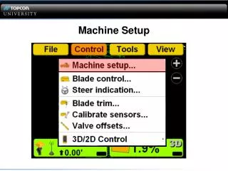
Machine Setup
Machine Setup. Webinar Information. This Webinar is LISTEN only. QUESTIONS?. Questions will be answered in writing at the end of the Webinar. Machine Setup (Machine Builder). Objectives of this lesson: Review all the screens and steps required to properly configure your Grader or Dozer.

Machine Setup
E N D
Presentation Transcript
Webinar Information • This Webinar is LISTEN only QUESTIONS? Questions will be answered in writing at the end of the Webinar.
Machine Setup (Machine Builder) • Objectives of this lesson: • Review all the screens and steps required to properly configure your Grader or Dozer.
Motorgrader Antenna Selection • Topcon Twin (MC-A2) will require additional calibration not covered in this Webinar
Motorgrader Antenna Selection CR-3 Rev 1 MC-A2 & MC-A1
Measurements When making all the measurements for a Grader or Dozer use + numbers unless the measurement is opposite of what's being asked.
Motorgrader Above • Above Measurement • Slant height • Front Antenna Rim
Motorgrader Above • Above Measurement • Slant height • Front Antenna Rim
Motorgrader Inside • Inside Measurement • Vertical Pole (side to side) • Offset from center of Pole
Motorgrader Inside • Inside Measurement • Vertical Pole (side to side) • Offset from center of Pole
Motorgrader Behind • Behind Measurement • Vertical Pole (front to back) • Offset from center of Pole
Motorgrader Behind • Behind Measurement • Vertical Pole (front to back) • Offset from center of Pole Error!
Motorgrader Behind • Behind Measurement • Vertical Pole • Offset from center of Pole
Motorgrader Width • Width Measurement • Blade length (width)
Motorgrader Width • Width Measurement • End to End
GPS Precisions • GPS Precisions • Position Quality RTK • Max. GPS errors (roving) • GPS status will flash orange if RMS values are exceeded • Max. GPS errors (point measurement) • Tolerance for topo survey and measure point feature
GPS Comms Configuration • GPS Cooms Configuration • Setup screen for GPS receiver
GPS Comms Configuration • Connection • Serial Port MC 2.5 • TCP/IP 9905 & 9906 MC-R3 with 160 Boards • UDP/IP 9907 & 9908 MC-R3 112 Boards (3D-MC2 all MC-R3 since mid Feb) MC 2.5 MC-R3
GPS Comms Configuration • IP Address/Port/Password • Settings programmed on the GNSS receiver • All boxes use the same settings the default button sets defaults 9905 & 9906 160 boards 9907 & 9908 112 boards MC 2.5
GPS Radio Configuration Used to configure radio type also accessed in the Tools menu
LD-40 Setup • Search finds all attached LD-40 light bars and will populate the ID box • Select an LD-40 from the ID pull down • With the LD-40 selected the Identify button will cause all the lights flash
LD-40 Setup • Location • Select how the LD-40 is to be used • Left edge (position information for the left edge to the design surface) • Right edge (position information for the right edge to the design surface) • Cut/Fill (will be the point you select on the blade in the blade control menu) • Slope (the difference from actual slope to design slope matches 9168 LEDs) • Steering (LD-40 being used as a steering indicator)
LD-40 Setup • Centered • If checked the On-Grade will be positioned in the center of the LD-40 • If unchecked the On-Grade will be positioned on the lower half of the LD-40 • Typical application for Excavators or scrapers making large cuts working down to grade
LD-40 Setup • Inverted • The Inverted option selects the correct orientation of the LD-40
LD-40 Setup • Precisions • Set the sensitivity of the LD-40 LEDs. • 1 Fine - 5 Coarse • 1=15mm (per LED) • 2=20mm (per LED) • 3=30mm (per LED) • 4=50mm (per LED) • 5=100mm (per LED)
LD-40 Setup • Colors • Changes the Cut/Fill colors. • Yellow over Red • Red over Blue
LD-40 Setup • Auto/2D • The operator can select to have the LED on the Left or Right LD-40 illuminate when the machine is in auto. The Auto Left/Right selection is for 3D mode. The 2D Left/Right selection is for 2D mode. • When operating a Grader both the Right and Left Auto switches need to be in auto for the LED to illuminate.
Dozer Sensor Selection Select the appropriate sensor
Dozer System 5 System 5 sensor MC Builder
Dozer System 5 Ensure the Antenna is perpendicular to the tracks on level ground when making machine measurements.
Dozer Above Above Measurement
Dozer System 5 • Above Measurement • Slant height • Front Antenna Rim
Dozer Inside Ensure the antenna is vertical
Dozer Inside • Ensure the antenna is vertical • Drop plum bob from center of the vibration pole • Measure from the Right side of the blade
Dozer Behind • Dozer Behind Measurement • Drop plum bob from center of the vibration pole • Measure distance behind