Download
1 / 28
280 likes | 643 Vues
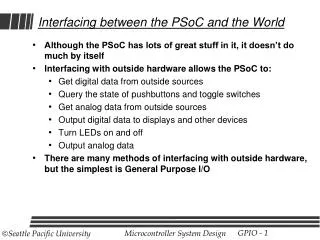
Although the PSoC has lots of great stuff in it, it doesn’t do much by itself Interfacing with outside hardware allows the PSoC to: Get digital data from outside sources Query the state of pushbuttons and toggle switches Get analog data from outside sources

E N D
Although the PSoC has lots of great stuff in it, it doesn’t do much by itself Interfacing with outside hardware allows the PSoC to: Get digital data from outside sources Query the state of pushbuttons and toggle switches Get analog data from outside sources Output digital data to displays and other devices Turn LEDs on and off Output analog data There are many methods of interfacing with outside hardware, but the simplest is General Purpose I/O Interfacing between the PSoC and the World
GPIO • General Purpose I/O refers to using individual port pins under program control • Output – CPU can set a pin high or low at any time • Input – CPU can read the value on a pin at any time • Example: To output a square wave on port2[0] • Set port2[0] low • Pause • Set port2[0] high • Pause • Repeat
The PSoC has up to eight eight-bit ports 29466 has three ports Port0 – Port2 29566 has five ports Port0 – Port4 29666 has six ports Port0 – Port5 29866 has eight ports Port0 – Port7 GPIO Ports
Three ports All can be used for digital I/O Ports 0 and 2 have some capacity for analog I/O Many pins have constraints for special-purpose use See Part-# Datasheet for details 29466 Ports
GPIO Configuration • The first step is to configure the port pins • Basic output mode called “Strong Drive” • Basic input mode called “Hi-Z” • Port pins may be configured individually, with mixed inputs and outputs in the same port • Two methods: • Using PSoC Designer • Easy, static (doesn’t change once set) • Using ASM Language commands • Slightly harder • Can change mode any time under program control • For ALL the details, see TRM B-6.
I/O Configuration using PSoC Designer Device Editor Pinout Window (Lower Left) Default is High-ZAnalog (input) StdCPU means portread/written by CPU Can rename portfor ease of use Select Drive Modefor each port pin Strong: Output Hi-Z: Input Details on other drive modes, connections, and interrupts later…
Basic Output using GPIO • First, configure port pin to an output mode • Strong drive is the basic output mode • Write ‘0’ or ‘1’ to appropriate bit in PRTxDR • Value will be output until changed • Example: Write a ‘1’ to Port1[4] • Assume Port 1 has been configured so that pin[4] is Strong Drive and all others are Hi-Z • MOV REG[PRT1DR], %00010000 • Other pins in port are ignored since they are Hi-Z (input) • Example: Write pattern “0101” to four low order bits of Port1 • Assume Port 1 has been configured so that pins[3,2,1,0] are Strong Drive and others are Hi-Z • MOV REG[PRT1DR], %00000101
Basic Input using GPIO • First, configure port pin to an input mode • Hi-Z Digital is the basic input mode • Read PRTxDR • Values of all port pins are copied to destination • Example: Read Port1[2] • Assume Port 1 has been configured so that pin[2] is Hi-Z • MOV A, REG[PRT1DR] // read all pins of port 1 • Other input pins will get the values currently on the pins, even if garbage • Output pins will get the value last written to them • Example: Loop as long as Port1[2] is low • LOOP: TST REG[PRT1DR],%00000100 JZ LOOP Warning – Hi-Z digital works well for inputs that produce nice 0’s and 1’s. Pushbuttons don’t do this and require a different mode. See slides on Port Modes below.
A word or two about Register Banks • PSoCs have 512 registers • Addressed by an 8-bit address (!) • Registers are arranged in two banks, each with 256 registers • REG[0] refers to two different registers, depending on which bank is selected • REG[0] = PRT0DR in bank 0, PRT0DM0 in bank 1 • Bank selection is made with the XIO bit in the FLAG register • Bit 4 of Flag Register = XIO = Current Register Bank • Select Reg Bank 0: AND F, %11101111 • Macro M8C_SetBank0 • Select Reg Bank 1: OR F, %00010000 • Macro M8C_SetBank1 • Convention – Normally in Bank 0 • If change to Bank 1, must change back to Bank 0 when done MOV REG[PRT1DM2], %11011011M8C_SetBank1 // set Bank 1MOV REG[PRT1DM1], %11111011MOV REG[PRT1DM0], %00000100M8C_SetBank0 // set Bank 0
Register References • All registers are described in TRM section C-13 • Bank zero register addresses listed as 0,xxh • 0,01h – Bank 0, REG[01] (PRT0IE) • Bank one registers addresses listed as 1,xxh • 1,03h – Bank 1, REG[03] (PRT0IC1) • Also, look at m8c.inc in “External Headers” of Application Editor in PSoC Designer • Browse around this file a bit to find useful macros
7 6 5 4 3 2 1 0 PRT1DM2 PRT1DM1 PRT1DM0 I/O Configuration using ASM Language • Drive mode registers select one of seven possible drive modes for each bit of each port • PRTxDM2 (bank 0), PRTxDM1 (bank 1), PRTxDM0 (bank 1) configure the bits for port x • Example: Set Port1[5] to Hi-Z (input) and Port1[2] to Strong Drive (output) Bank 0 1 1 0 1 1 0 1 1 1 1 1 1 1 0 1 1 0 0 0 0 0 1 0 0 Bank1 M8C_SetBank0MOV REG[PRT1DM2], %11011011M8C_SetBank1MOV REG[PRT1DM1], %11111011MOV REG[PRT1DM0], %00000100M8C_SetBank0 DM2 = Hi-Z (digital input) DM6 = Hi-Z Analog (default) DM6 = Hi-Z Analog (default) DM6 = Hi-Z Analog (default) DM6 = Hi-Z Analog (default) DM6 = Hi-Z Analog (default) DM6 = Hi-Z Analog (default) DM1 = Strong Drive (output)
Bi-Directional Ports • Some devices use bi-directional pins • Memory data busses, for example • PSoC port pins can be dynamically reconfigured as inputs or outputs • Useful to setup Macros to change the direction of a port on the fly • MACRO Port3InputM8C_SetBank0 • MOV REG[PRT3DM2], %00000000M8C_SetBank1MOV REG[PRT3DM1], %11111111MOV REG[PRT3DM0], %00000000M8C_SetBank0ENDM • MACRO Port3OutputM8C_SetBank0 • MOV REG[PRT3DM2], %00000000M8C_SetBank1MOV REG[PRT3DM1], %00000000MOV REG[PRT3DM0], %11111111M8C_SetBank0ENDM • Can simply use “Port3Input” or “Port3Output” in source code now
To PSoCInput Logic To PSoCInput Logic Port Modes: Strong and Slow Strong VCC VCC Port Pin Port Pin FromPSoCCore FromPSoCCore GND GND Slow Strong Drive Mode Strong Drive Mode Controlled rise/fall times.Rise/Fall times 10-25ns. Saves power Normal output mode. Works like an inverter. Rise/Fall times 3ns-18ns
VCC VCC To PSoCDigital Input Logic To PSoCAnalog Input Logic Port Pin Port Pin GND GND Port Modes: Hi-Z and Analog Hi-Z Hi-Z Mode Analog Hi-Z Mode Digital Input Mode Analog Input Mode. Select when port is unusedsince it consumes no power.
To PSoCInput Logic VCC To PSoCInput Logic Port Pin 5.6K 5.6K Port Pin Port Modes: Resistive Pull-Up and Pull-Down VCC VCC To PSoCInput Logic To PSoCInput Logic 5.6K Port Pin Port Pin FromPSoCCore 5.6K FromPSoCCore GND GND Resistive Pull-Down Resistive Pull-Up Effective Circuit if written with ‘0’ Effective Circuit if written with ‘1’ WARNING:If you are using this mode as input-only, make sure to write correct value to port!
Button VCC Button VCC 5.6K To PSoCInput Logic Port Pin 5.6K Switches and Pushbutton Inputs SPST Button:Produces either Vccor Floating input. Adding a pull-downresistor fixes it. PSoC port inPull-Down mode Don’t Forget:Write ‘0’ to port
Monitoring External Events - Polling • How does the CPU know if an external event has happened? • Button pushed down • Incoming signal on a line • Alarm signal • Etc. • How do people do this? Polling – repeated checking. • Sentries on watch • Waiting for someone • Waiting for class to end…
Detecting a Pushbutton Input • Connect a pushbutton to an input port • Make sure it is hooked up so it produces a ‘1’ when pressed. Use pull-down mode if needed. • Write a loop that checks if the port pin is ‘1’ • Example: Button connected to Port1[3] • MOV REG[PRT1DR],0 // make sure input pin is pulled down MOV [COUNT],0LOOP: TST REG[PRT1DR], %00001000 // check if port1[3] is 1 JZ LOOP // not 1, keep checking (polling) INC [COUNT] // button pressed – act on it // output COUNT to LCD JMP LOOP Will increment multipletimes for each button press
time Pressed Released IncCOUNT DisplayCOUNT Pollfor 1 IncCOUNT DisplayCOUNT Pollfor 1 Multiple Counts per Press Displays ‘1’ Displays ‘2’ • Solution: After acting on button, “eat up” 1’s • MOV REG[PRT1DR],0 // make sure input pin is pulled down MOV [COUNT],0ZeroLOOP: TST REG[PRT1DR], %00001000 // check if port1[3] is 1 JZ LOOP // not 1, keep checking (polling) INC [COUNT] // button pressed – act on it // output COUNT to LCDOneLOOP: TST REG[PRT1DR], %00001000 // check if port1[3] is 1 JNZ OneLOOP // poll to “eat up” excess 1’s JMP LOOP
Button VCC 5.6K Bouncing Switches time Pressed Released • Switches are mechanical objects • Contacts will bounce up and down when moved • Produces a series of short pulses • A bouncy switch may cause multiple events to be triggered each time it is pressed
De-bouncing • De-bouncing switches is critical to most systems • Solutions may involve hardware changes or software changes • Hardware: • Build hardware that gets rid of the bounce • Works well, but costs $$$, space and power • Software: • Write software to ignore bounces • Cheap, but harder to fine-tune
Pushbutton Single-Pole Double-Throw (SPDT) Switch Input R Q R Q GND +5 De-BouncedOutput S Q Q S GND Hardware De-Bounce with R-S Latch Prior De-Bounced
Button VCC 5.6K Hardware De-Bounce with RC Circuit Prior • Use an RC circuit to slow down the rise time • Can also view as filtering out high-frequency response • Requires a carefully-sized capacitor, matched with the resistor ($) • Slows down response time De-Bounced
25ms 25ms Software De-Bounce • Whenever a change in the input value is detected, ignore the input for some period of time afterward • Example: Delay 25ms after input changesMOV REG[PRT1DR],0 // make sure input pin is pulled down MOV [COUNT],0ZeroLOOP: TST REG[PRT1DR], %00001000 // check if port1[3] is 1 JZ LOOP // not 1, keep checking (polling) INC [COUNT] // button pressed – act on it // output COUNT to LCDCALL DELAY_25MS // ignore switch for 25msOneLOOP: TST REG[PRT1DR], %00001000 // check if port1[3] is 1 JNZ OneSLOOP // poll to “eat up” excess 1’sCALL DELAY_25MS // ignore switch for 25ms JMP LOOP
Design Issues with Software De-Bounce • If the de-bounce delay is too long… • Response time may be impaired • May miss some real inputs • User will be unhappy • If the de-bounce delay is too short… • Some inputs will be counted twice • User will be unhappy • Always make de-bounce delay as long as is tolerable • Switches may become bouncier as they age • Manufacturer may replace switches with a bouncier type
How to make a time delay • First solution – make a long loopDELAY: MOV A, 255 NOP NOP … DEC A JNZ DELAY RET • Problems • Time delay depends on clock speed – may change • Time delay depends on CPI – may change • Icky to compute just how long delay is
How to make a time delay • Second solution – use a built-in timer • PSoC has several timers – one is the Sleep Timer • Sleep Timer designed as an alarm clock to wake up the system periodically. May be used as a general “alarm clock” • Sleep Timer counts “ticks” of its input clock • System calls allow delaying for a number of ticks • Input clock can be selected to:1 Hz – 1 sec/tick8 Hz – 125 ms/tick64 Hz – 15.6 ms/tick512 Hz – 1.95 ms/tick • SleepTimer_TickWait(ticks) delays for a number of ticks
Sleep Timer API • The sleep timer relies on interrupts for it operation (more on them later) • Code must enable interrupts both Globally (for the PSoC) and specifically for the Sleep Timer • Example code to delay approximately 25 ms • (25 ms / 1.95 ms is around 13 ticks)_main: M8C_EnableGInt ; Turn on interrupts call SleepTimer_Start ; Start SleepTimer mov A, SleepTimer_512_HZ ; Use 512 Hz interrupt rate call SleepTimer_SetInterval call SleepTimer_EnableInt ; Enable SleepTimer Interrupt Loop: mov A,13 ; Set tick delay to 13 ticks lcall SleepTimer_TickWait ; Delay for 13 ticks (25 ms) ; Put main loop user code here jmp Loop