
Power Transformers
E N D
Presentation Transcript
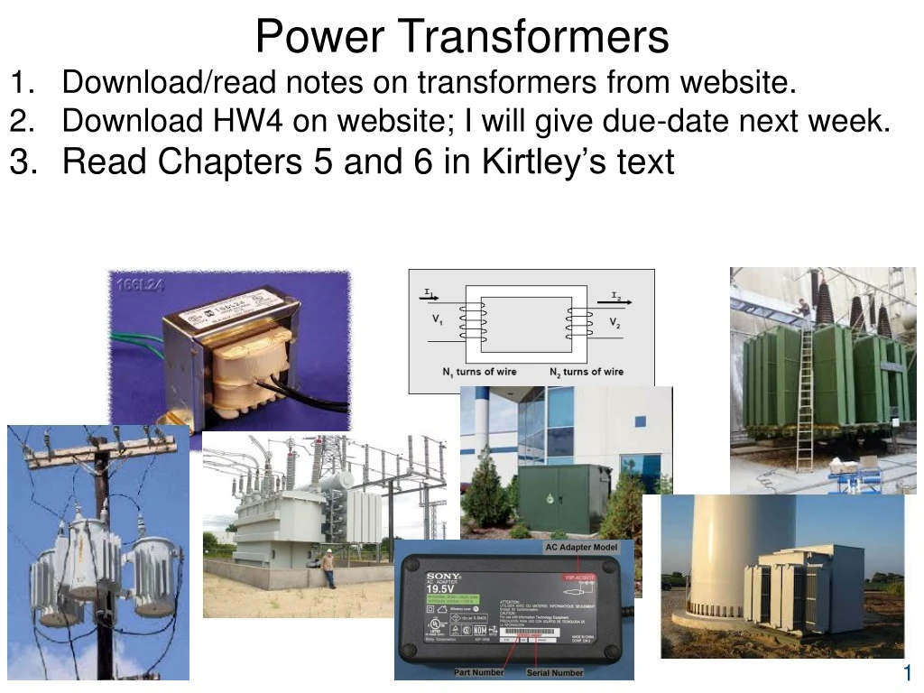
Power Transformers Download/read notes on transformers from website. Download HW4 on website; I will give due-date next week. Read Chapters 5 and 6 in Kirtley’s text
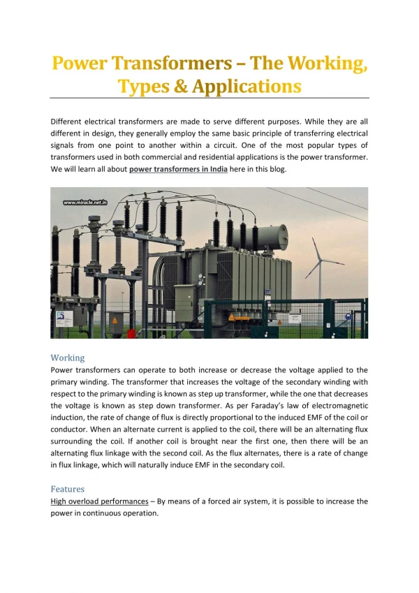
Power Industry Uses of Transformers Instrument Transformers: Current (CT) and potential (PT) transformers: Step down quantity from power system level (gen, trans, dist) so that quantity is compatible at the instrument level, in order to perform protective relaying (you need to take EE 457 to learn about these). Power Transformers: Step up voltage from generator to transmission (GSU) Step down voltage from transmission to distribution primary levels Step down voltage from distribution primary to distribution secondary Interconnecting different system voltage levels in HV and EHV systems
Magnetic circuits Ampere’s Law: Line integral of mag fld intensity about a closed path equals current enclosed. Apply it here: • Make the path the dotted line. • H is along direction of ϕ, which is same direction as dL • Let l be length of dotted path, therefore LHS is Hl • RHS is current enclosed: Ni.
Magnetic circuits Recall
Magnetic circuits Define: magnetomotive force (MMF): reluctance: This looks suspiciously familiar. What does this remind you of? Write down the relations for F, R, and ϕ.
Magnetic circuits Units: ϕ webers (kg-m2/sec2/Amp) B webers/m2=tesla F ampere-turns R amperes/weber μ =μrμ0=μr(4π×10-7)Ntn/Amp2
Example Compute ϕ.
Inductance Recall: Define: Flux Linkage: Self Inductance:
Inductance Some notation that will be useful later: • The self inductance L11 is the ratio of • the flux from coil 1 linking with coil 1, λ11 • to the current in coil 1, i1 Linking? … Passing through the coil interior
Inductance Flux not linking Flux linking
Inductance Some notation that will be useful later: • The self inductance L11 is the ratio of • the flux from coil 1 linking with coil 1, λ11 • to the current in coil 1, i1 Inductance L11? The ability of a current in coil 1, i1, to create flux φ11 that links with coil 1.
Inductance • To make large self-inductance, we need to • make N1, μ, and A large; • make l small • And so a large L11 results from • many turns (N1) • large μ (core made of iron) • large cross section (A) • compact construction (small l)
And so a large L11 results from • many turns (N1) • large μ (core made of iron) • large cross section (A) • compact construction (small l) Recalling we see that a magnetic circuit characterized by a large self-inductance will have a small magnetic path reluctance.
Example Example 2: Compute the self-inductance of the magnetic circuit given in Ex 1. We just found that Alternative derivation:
Example Example 2: Compute the self-inductance of the magnetic circuit given in Ex 1. From Ex 1, N1=100 and
φ i2 i1 N1 N2 Mutual inductance From our self-inductance work, we express for each coil • where we recall the self inductance Ljj is the ratio of • the flux from coil j linking with coil j, λjj • to the current in coil j, ij
Mutual inductance λjj • The self inductance Ljj is the ratio of • the flux from coil j linking with coil j, λjj • to the current in coil j, ij λij • Likewise, mutual inductance Lij is the ratio of • the flux from coil j linking with coil i, λij • to the current in coil j, ij
Mutual inductance λ12 • Mutual inductance L12 is the ratio of • the flux from coil 2 linking with coil 1, λ12 • to the current in coil 2, i2 λ21 • Mutual inductance L21 is the ratio of • the flux from coil 1 linking with coil 2, λ21 • to the current in coil 1, i1
Mutual inductance Recall that Likewise And the mutual inductances become
This leakage flux is assumed to be zero. φ i2 i1 N1 N2 Mutual inductance Assumption: All flux produced by each coil links with the other coil. This implies there is no leakage flux. In reality there is some leakage flux, it is quite small because the iron has much less reluctance than the air With no leakage flux, it must be the case that all flux developed by one coil must completely link with the other coil.
Mutual inductance • If all flux developed by one coil completely links with the other coil, then • the flux from coil 2 linking with coil 1 is equal to the flux from coil 2 linking with coil 2, i.e., • the flux from coil 1 linking with coil 2 is equal to the flux from coil 1 linking with coil 1, Substitute above into slide 20 inductance expressions:
Mutual inductance Comparing the above leads to • This says that the mutual inductances are reciprocal: • The ratio of • flux from coil 2 linking with coil 1, λ12, to i2 • is the same as the ratio of • flux from coil 1 linking with coil 2, λ21, to i1
Mutual inductance We showed on slide 14 that Solve for N1 and N2: Substitute into slide 22 mutual inductance expression:
Mutual inductance It is conventional to denote mutual inductance as M: • Mutual inductance gives the ratio of: • flux from coil k linking with coil j, λjk • to the current in coil k, ik,
φ11 φ21 i2 i1 e2 N1 N2 v1 e1 Polarity & dot convention for coupled ccts Open cct DC voltage We have a dial to increase v1 Coil 1: very small resistance so in steady-state, i1≠∞ Increase voltage v1 to some higher value current i1 increases with time flux from coil 1, φ11, increases with time flux linkages λ11increases with time. Who speaks when you have dλ/dt (=d(Nϕ)/dt)≠0?
φ11 φ21 i2 i1 e2 N1 N2 v1 e1 Polarity & dot convention for coupled ccts Who speaks when you have dλ/dt (=d(Nϕ)/dt)≠0? Faraday! But what about the sign of the right-hand-side (RHS)? Is it positive or negative?
φ11 φ21 i2 i1 e2 N1 N2 v1 e1 Polarity & dot convention for coupled ccts But what about the sign of the right-hand-side (RHS)? Is it positive or negative? The sign of RHS is positive because self-induced voltage across a coil is always positive at terminal the current enters, &e1 is defined positive at this terminal. If e1 would have been defined negative at terminal in which the current entered, then sign of RHS would be negative.
φ11 φ21 i2 i1 e2 N1 N2 v1 e1 Polarity & dot convention for coupled ccts If e1 would have been defined negative at terminal in which the current entered, then sign of RHS would be negative.
φ11 φ21 i2 i1 e2 N1 N2 v1 e1 Polarity & dot convention for coupled ccts Now consider coil 2… it sees same flux that coil 1 sees which we denote by φ21 (and correspondingly, the flux linkages are denoted as λ21). Considering our action of using the dial to increase v1, we again have, by Faraday’s Law, Is the sign of RHS positive or negative?
φ11 φ21 i2 i1 e2 N1 N2 v1 e1 Polarity & dot convention for coupled ccts Is the sign of RHS positive or negative? That is, how do we know which of below are correct?
φ11 φ21 i2 i1 e2 N1 N2 v1 e1 Polarity & dot convention for coupled ccts That is, how do we know which of below are correct? Alternatively: Does assumed e2 polarity match actual polarity of voltage induced by changing current i1? If yes, we choose positive sign. If not, we choose negative sign.
φ11 φ21 i2 i1 e2 N1 N2 v1 e1 Polarity & dot convention for coupled ccts That is, how do we know which of below are correct? Use Lenz’s Law: induced voltage e2 must be in a direction so as to establish a current in a direction to produce a flux opposing the change in flux that produced e2. See www.khanacademy.org/science/physics/magnetic-forces-and-magnetic-fields/magnetic-flux-faradays-law/v/lenzs-law
φ11 φ21 i2 i1 e2 N1 N2 v1 e1 Polarity & dot convention for coupled ccts When e1 increases, i1 increases, and by the right-hand-rule (RHR), φ21 increases. Assumed polarity of e2 causes current to flow into the load in direction shown. How do we know e2polarity is correct? Use Lenz’s Law: induced voltage e2 must be in a direction so as to establish a current in a direction to produce a flux opposing the change in flux that produced e2.
φ11 φ21 i2 i1 e2 N1 N2 v1 e1 Polarity & dot convention for coupled ccts We know e2 polarity is correct because RHR says that a current in direction of i2causes flux in direction opposite to the direction of the φ21increase. This is “the φ21increase,” i.e., it is “the change in flux that produced e2” and not necessarily the direction of φ21itself (in this particular case, “the φ21increase” is the same as the direction of φ21itself).
φ11 φ21 i2 i1 e2 N1 N2 v1 e1 Polarity & dot convention for coupled ccts We know e2 polarity is correct because RHR says that a current in direction of i2causes flux in direction opposite to the direction of the φ21increase. Question: How might we obtain a different answer?
φ11 φ21 i1 e2 N1 N2 v1 e1 i2 Polarity & dot convention for coupled ccts There are two ways. First way: Switch sign of e2, as above. Here, we also must switch current i2direction, because, in using Lenz’s Law, the i2 direction must be consistent with the e2direction. Here, the current i2, by RHR, produces a flux in the same direction as the φ21 increase, in violation of Lenz’s Law:
φ11 φ21 i2 i1 e2 N1 N2 v1 e1 Polarity & dot convention for coupled ccts There are two ways. Second way: Switch the sense of the coil 2 wrapping, while keeping the directions of e2 and i2 as they were originally. The current i2, by RHR, produces flux in same direction as the φ21 increase. Therefore
φ11 φ21 i2 i1 e2 N1 N2 v1 e1 Polarity & dot convention for coupled ccts Let’s articulate what we are trying to do: We want to know which secondary terminal, when defined with positive voltage polarity, results in using Faraday’s Law with a positive sign. On paper, there are 2approaches for doing this. 1. Draw the physical winding go through Lenz’s Law analysis as we have done in previous slides.
φ11 φ21 i2 i1 e2 N1 N2 v1 e1 Polarity & dot convention for coupled ccts On paper, there are 2approaches for doing this. Draw the physical winding; go through Lenz’s Law analysis as we have done in previous slides. Use the “dot convention.” • In dot convention, we mark 1terminal on each coil so that • when e2 is defined positive at dotted terminal of coil 2 • and i1is into the dotted terminal of coil 1, then
Example Ex 3: Express the voltage for each pair of coils below. • From previous slide: In dot convention, we mark 1 terminal on each coil so that • when e2 is defined positive at dotted terminal of coil 2, and • i1is into the dotted terminal of coil 1, then i1 e2 3 3 i1 e2 (1) Recall the sign on the RHS is determined not by direction of flux flow (or current i1 flow) but by direction of change in flux flow (or current i1 flow). (2) Our above dot convention seems to depend only on direction of current (i1) flow and not on direction of change in current flow. 3 3 i1 e2 3 3 Question: How can our dot convention give correct sign if it does not account for direction of change in current i1 flow? i1 Answer: It does account for direction of change in current flow in that the above e2 equation implies positive direction of change (di1/dt is positive). e2 3 3
A second question So far, we have focused on answering this question: Given dotted terminals, how to determine the sign to use in Faraday’s law? A second question: If you are given the physical layout, how do you obtain the dot-markings? Approach 1: Use Lenz’s Law and the right-hand-rule (RHR) to determine if a defined voltage direction at the secondary produces a current in the secondary that generates flux opposing the flux change that caused that voltage. (This is actually a conceptual summary of Approach 2 below.)
A second question If you are given the physical layout, how do you obtain the dot-markings? Approach 2: Do it by steps. (This is actually a step-by-step articulation of the first approach.) • Arbitrarily pick a terminal on one side and dot it. • Assign a current into the dotted terminal. • Use RHR to determine flux direction for current assigned in step 2. • Arbitrarily pick a terminal on the other side and assign a current out of(into) it. • Use RHR to determine flux direction for current assigned in Step 4. • Compare the direction of the two fluxes (the one from Step 3 and the one from Step 5). If the two flux directions are opposite(same), then the terminal chosen in Step 4 is correct. If the two flux directions are same(opposite), then the terminal chosen in Step 4 is incorrect – dot the other terminal. This approach depends on the following principle (consistent with words in italics in above steps): Current entering one dotted terminal and leaving the other dotted terminal should produce fluxes inside the core that are in opposite directions. An alternative statement of this principle is as follows (consistent with words in underline bold in above steps): Currents entering the dotted terminals should produce fluxes inside the core that are in the same direction.
i1 e2 N1 N2 Example Example 4: Determine the dotted terminals for the configuration below, and then write the relation between i1 and e2. Remember: Current entering one dotted terminal and leaving the other dotted terminal should produce fluxes inside the core that are in opposite directions.
φ11 φ11 i1 i1 e2 e2 N1 N1 N2 N2 φ22 i2 Example Example 4: Determine the dotted terminals for the configuration below, and then write the relation between i1 and e2. Solution: Steps 1-3: Remember: Current entering one dotted terminal and leaving the other dotted terminal should produce fluxes inside the core that are in opposite directions. Steps 4-6:
φ11 i1 e2 N1 N2 φ22 i2 Example Example 4: Determine the dotted terminals for the configuration below, and then write the relation between i1 and e2. Solution: • Now write equation for the coupled circuits. Recall that in dot convention, we mark 1 terminal on either side of transformer so that • when e2 is defined positive at the dotted terminal of coil 2 and • i1 is into the dotted terminal of coil 1, then Here, however, although i1is into the coil 1 dotted terminal, e2 is defined negative at the coil 2 dotted terminal. Therefore
i2 e2 e2 N1 N1 N2 N2 i'1 i'1 φ11 φ22 φ11 Example Example 4: Determine the dotted terminals for the configuration below, and then write the relation between i1 and e2. Solution: there is another way we could have solved this problem, as follows Steps 1-3: Steps 4-6:
i2 e2 N1 N2 i'1 φ22 φ11 Example Example 4: Determine the dotted terminals for the configuration below, and then write the relation between i1 and e2. Solution: There is another way we could have solved this problem! • Write equation for the coupled circuits. Recall that in dot convention, we mark 1 terminal on either side of transformer so that • when e2 is defined positive at the dotted terminal of coil 2 and • i1 is into the dotted terminal of coil 1, then Here, i’2is into the coil 1 dotted terminal, e2 is defined positive at the coil 2 dotted terminal. Therefore If, however, we wanted to express e2 as a function of i1 (observing that i1=-i'1) then we would have
Example Example 5: For the configuration below, determine the dotted terminals and write the relation between i1 and e2. Note: Problems 1a,b,c,d are very similar to this one.
Example Example 5: For the configuration below, determine the dotted terminals and write the relation between i1 and e2. Solution: Steps 1-3: Steps 4-6: Here we arbitrarily assign dot to upper terminal of coil 2; then, with i2 out of this dotted terminal, we use RHR to determine flux φ22 is in same direction as coil 1 flux. This means our choice of coil 2 terminal location dot is wrong. Therefore we know dot must be at other terminal, and the below shows clearly this is the case, since the flux from coil 2, φ22, is opposite to the flux from coil 1, φ21.