Download

1 / 42
450 likes | 520 Vues
Explore human arm anatomy, prosthetic arm details, build a model, learn about bones, joints, muscles, gestures, and more with this educational agenda for seniors. Hands-on activities included.

E N D
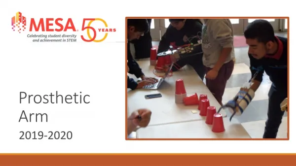
Prosthetic Arm Senior MESA Day
Agenda • Overview of the Human Arm Anatomy • Bones, Joints, Muscles • Review Arm Motion • Kinematics: types of motion, location of motion, direction of motion, magnitude of motion, and degrees of freedom • Kinetics: extrinsic forces, intrinsic forces, force vectors, force of gravity, reaction forces, additional linear forces, and classes of levers • Overview of the Prosthetic Arm • Building the Model • Building the Display
Bones of the Upper Extremity • Humerus • The longest and largest bone in the upper extremity. • Ulna • A long bone in the forearm parallel with the radius; at the proximal is the elbow and the distal end is the wrist. • Radius • The other bone of the forearm, shorter than the ulna.
Bones of the Hand • Carpals • The wrist is composed of 8 separate carpal bones. • Metacarpals • The intermediate part of the hand skeleton that is between the carpals and the phalanges (up to the knuckles); 5 metacarpal cylindrical bones • Phalanges • The fingers of the hand contain 14 digital bones.
Joints • Elbow Joint/Complex • Humeroulnar Joint – simple hinge-joint • Humeroradial Joint – arthrodial joint allowing gliding and sliding motions • Proximal Radioulnar Joint – pivot joint • Wrist Joint • Radiocarpal joint • Carpometacarpal joints • Intercarpal joints intercarpal joints carpometacarpal joint midcarpal joint radiocarpal joint
Metacarpophalangeal Joints • Interphalangeal Joints interphalangeal joints
Movements • Flexion: decreasing joint angle such as bending • Extension: increased joint angle such as stretching • Abduction: movement that draws limb away from sagittal plane • Adduction: movement which brings limb closer to the sagittal plane • Supination: palm faces up • Pronation: palm faces down • Circumduction: combination of flexion, extension, abduction and adduction
Muscles • Upper Arm • Biceps brachii, brachialis, coracobrachialis • Forearm • Flexor-pronator and extensor-supinator • Hand • Thenar, hypothenar, interosseous, lumbrical
Tendons • Tough bands of fibrous connective tissue that connects muscles to bones. • Capable of withstanding tension • Function to transmit force • Function as springs
Activity 3: Fingers of the Hand • Purpose: To understand and demonstrate the bones, tendons and muscles of the hand Lesson plan courtesy of: Curt Gabrielson Watsonville Community Science Workshop
One Finger • Cut a full length popsicle stick into 1/3 pieces • Cut 3 pieces of straw slightly shorter than sticks • Glue pieces of straw to stick pieces • Glue all three segments onto a full straw; leave a small space in between each segment, so that flexing is possible • Glue 3 segments with full straw end to a full length stick • Glue one more straw segment onto the top of the full length stick in line with other 3 segments • Tie a bead to the end of piece of string and thread other end through all 4 short straw segments • Tie bead to other end. Wrap each segment with tape.
Whole Hand • Cut a paint paddle in half, then one half into two pieces, one about an inch shorter than the other • Glue the larger piece to the top of the full half to form a “T”. Glue smaller piece right underneath it. • Make three more fingers and a thumb • Glue the fingers to the paint paddle frame • Glue on the thumb more towards the side of the side of the hand • Each finger should move when pulling on its string
Arm Motion - Kinematics • Types of Motion • Translatory: all parts move toward same direction • Rotatory/Angular: around a fixed axis • General: combination of translation and rotation • Location of Motion • Transverse or Horizontal Plane • Superior and Inferior • Coronal or Frontal Plane • Anterior and Posterior • Sagittal plane • Medial and Lateral
Rotatory motion occurs around a fixed axis. y - vertical axis x - coronal axis z – sagittal axis
C 3.6 m 3 m 2 m B A • Magnitude of Translatory Motion • Displacement: change of position that an object moves from the reference point • Velocity: rate of change in displacement • v = dx / dt • Acceleration: rate of change in velocity over time • A = dv / dt
Magnitude of Rotatory Motion • Angular displacement: rotation of an object about an axis in radians Δθ = Δθ2 − Δθ1 • Angular velocity: time rate at which an object rotates about an axis, or at which angular displacement between two bodies changes • Angular acceleration: change of angular velocity over time
Degrees of Freedom • 3 translatory motions along the x, y, and z axes and 3 rotatory motions around the x, y, and z axes • 6 DOF of a rigid body • Moving up and down • Moving left and right • Moving forward and backward • Tilting forward and backward (pitch) • Turning left and right (yaw) • Tilting side to side (roll)
Activity 7: Degrees of Freedom • Purpose: to understand degrees of freedom in biomechanics
Fill standard coffee mug with water ¾ full • Place empty bucket on table. Using your hand, grab and lift the cup and pour the water into the bucket • How many different positions can you pour the water without spilling? • Restricting a DOF at the shoulder joint, grab and lift the cup and pour the water • Restricting a DOF at the elbow joint, grab and lift the cup and pour the water • Restricting a DOF at the wrist joint, grab and lift the cup and pour the water • Record observations on Activity Sheet (page 41 of curriculum)
Activity 8: Build a Paper Robot Arm • Purpose: to build a paper robot arm and demonstrate the degrees of freedom Activity developed by Pre College Programs, USC Viterbi School of Engineering
Carefully cut out humerus, radius/ulna, and carpal • Bend along lines to form arm segments • Using push pin, poke holes where indicated • Line up holes of humerus with holes of radius/ulna and insert fastener through both sides • Line up holes of radius/ulna with holes of carpal and insert fastener through both sides • Cut one strip of foam board 4" x 2", one strip 3" x 2", and two small pieces 1" x 2" • Create standing post • Tape free side of humerus to top of standing post • Tape a string to the proximal end of radius/ulna • Insert paper clip through top of standing post and bring free end of humerus string through clip
Questions for Analysis • How many degrees of freedom does your paper robot arm possess? • Using a protractor, determine the actual degrees of movement. • Determine the angular displacement
Part II: • Using what you learned in Part I, design and create another paper robot are that has three or more degrees of freedom. You can modify the existing paper robot arm or you can create a new paper robot arm • Questions for Analysis: • How many DOF does your new paper robot arm have? • Describe the DOF. • Using a protractor, determine the actual degrees of each movement. • Determine the angular displacement for each DOF. • What was different in design of your new paper robot arm that allowed for additional DOF?
Arm Motion - Kinetics • Extrinsic Forces • Gravitation force • Fluid force • Contact forces • Intrinsic Forces • Include muscles, ligaments, and bones • Friction between articular surfaces • Tension of antagonistic muscles, ligament, fasciae, and capsules • Atmospheric pressure within the join capsule
Concepts to Consider: • Force Vectors • Point of application, action line and direction and magnitude • Force of Gravity • Gives an object weight, the magnitude of force that must be applied to an object in order to support it in a gravitational force • Weight = mass x 9.8 m/s2 or 32.2 ft/s2 • Center of mass: the point where all of the mass of an object is concentrated
Equilibrium • Law of Inertia: every object persists in its state of rest or uniform motion in a straight line unless it is compelled to change that state by forces impressed on it • ∑ F = 0 • Law of Acceleration: acceleration is produced when a force acts on a mass; directly proportional to force and inversely proportional to mass • a = F/ m • Reaction Forces • Law of Reaction: for every action, there is an equal and opposite reaction
Additional Linear Forces • Tension: pulling force exerted when an object is being stretched or elongated • Compression: force applied to an object tending to cause a decrease in volume • Shear: force that moves or attempts to move on another object • Torque: the tendency of a force to rotate an object about an axis or τ = (F) (moment arm) • Moment Arm = ⊥d In A, what is the moment arm? In B, what is the moment arm?
Classes of Levers • First-class levers: effort force and resistance force located on opposite sides of axis of rotation • Second-class levers: effort force located at the end of bar and fulcrum located at other end, with the resistance force at a point between these two forces • Third-class levers: effort force is applied between the resistance force on one end the fulcrum on the opposite end • Law of the Lever: Effort Arm x Effort Force = Resistance Arm x Resistance Force EA = distance effort force lies from axis of rotation RA = distance resistance force lies from axis of rotation
Mechanical Advantage (MA) • Factor by which a mechanism multiplies the force or torque put into it; • Ratio of effort arm (EA) to the resistance arm (RA) • A second-class lever will always have a MA > 1 because EA > RA • A third-class lever will always have a MA < 1 because EA < RA • common in the body and the MA is poor; however, the speed of rotation created is high because the origin of the resistance force is located farther from the axis rotation than the origin of the effort force, it must travel a greater distance in the same time • A first-class lever can have a MA <, =, or > than 1, depending on the locations of the effort force and resistance force versus the axis of rotation
Activity 10: Wooden Hydraulic Robot Arm • Purpose: To create a wooden robot arm with three degrees of freedom that uses hydraulics for motion Activity developed by Pre College Programs, USC Viterbi School of Engineering Safety Procedure: Use extreme caution with using sharp tools, drills, and hot glue gun
Cut two 6”x3” plywood long rectangles, a 4”x2½ “ plywood medium rectangle, and a 2½”x 2½” plywood square • Round off corners of each piece w/sandpaper • Humerus: in the middle of one of the long rectangles, drill three holes • Radius/ulna: in the middle of the other long rectangle, drill two holes • Carpal: in the middle of the medium rectangle, drill one hole and one large hole in the center • Line up single hole of humerus with hole of radius/ulna and insert bolt and nut • Line up remaining hole of radius/ulna with small hole of carpal and insert bolt and nut
Standing Post and Platform Standing Post • Cut a strip of plywood 10”x3” and two small pieces of plywood 1”x3” • On the large strip, drill two holes • Create the standing post by gluing the two small pieces on both bottom sides of the large plywood • Line up holes of standing post with holes of humerus and insert bolts and nuts • Using the center of mass, determine the dimensions of the platform in order to balance the standing post and the arm structures with nuts and bolts • Cut plywood to determined dimensions above • Glue standing post vertically to platform Platform
Three DOF • Determine the best manner in attaching the syringes, plastic tubing, and film canister tops in order to create 3 DOF, taking into consideration the center of mass, torque and classes of levers. You may use additional materials if needed. • Questions for Analysis • Calculate the work done by lifting a 147.87 ml (5 oz) dixie cup filled with 100 ml of water to a height of 10 cm. Hint: • Calculate the torque using the above parameters. Hint: use • What class of lever is the wooden hydraulic robot arm? What are the advantages/disadvantages?
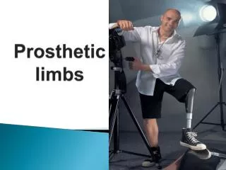
Prosthetic Arm • Artificial limb is a type of prosthesis, an artificial substitute, that replaces a missing extremity such as an arm • Needed for a various reasons, including disease, accidents, and congenital defects • History • Roman Capua Leg, found in a tomb in Capua, Italy dating to 300 BC, was made of cooper and wood • Armorers in the 15th and 16th centuries made artificial limbs out of iron for soldiers who lost limbs
Types • Transradial prosthesis: artificial limb that replaces an arm missing below the elbow • Transhumeral prosthesis: one that replaces an arm above the elbow • Current Technology • New plastics and other materials, such as carbon fiber, have allowed artificial limbs to be stronger and lighter • Additional materials allow for a more realistic look • Myoelectric limbs allow more direct control • Emerging Technology • Robotic limbs
Activity 11: Build Your Own Robot Arm • Purpose: to learn design concepts, teamwork, problem solving techniques and about simple machines • Goal: must be 18 inches in length and be able to pick up an empty Styrofoam cup Developed by IEEE as part of TryEngineering
Building the Model • Model MUST perform 3 tasks: grab, lift, and pour 50ml graduated cylinder with 50ml of sand • Model MUST be operated by push of button(s), pull of string(s), push or pull of syringe(s), etc. May NOT perform actual function of grabbing, lifting, or pouring • Entire base of model MUST fit within a 1.5 foot square. Any part of model that may be in contact with the table MUST be within the 1.5 foot square. • Use materials found around the house or school, taking into consideration cost and weight efficiency (max points awarded for low cost and low weight)
Building the Display • Dimensions: 3 ft x 3 ft x 2 ft deep • Freestanding • Synopsis of project, 200 to 250 words • Include purpose of project, explanation of model, and scientific and engineering ideas involved • Scaled plan rendering • Three separate 8 ½ x 11 scaled drawings (front, side, and top views) with dimensions • Materials Table • Table of all materials used in the model including retail price, price per unit, quantity used, total cost, and how each material was acquired (see rules for sample)