Download
1 / 28
300 likes | 437 Vues
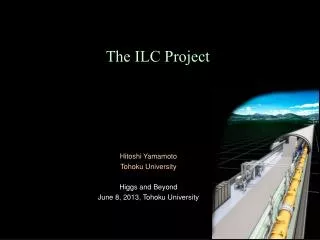
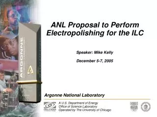
ANL Proposal to Perform Electropolishing for the ILC. Speaker: Mike Kelly December 5-7, 2005. Joint ANL/FNAL Cavity Processing Facility. Electropolishing at Argonne. Argonne has electropolished ~150 SC niobium cavities Cavity performance at ANL using EP is directly relevant to ILC

E N D
ANL Proposal to Perform Electropolishing for the ILC Speaker: Mike Kelly December 5-7, 2005
Electropolishing at Argonne • Argonne has electropolished ~150 SC niobium cavities • Cavity performance at ANL using EP is directly relevant to ILC • Experience with various geometries is directly applicable to ILC • Major infrastructure for EP of large SC cavities is in place
Outline Cavity Processing at ANL Cavity Performance An ANL Proposal for the ILC Technical Issues with 9-cell EP
I. Cavity Processing:High Performance SC Structures for RIA 345 MHz =0.40 Double-spoke 115 MHz =0.15 Steering-Corrected QWR 172.5 MHz =0.26 HWR 345 MHz =0.62 Triple-spoke 57.5 MHz QWR-based structures 0.03< <0.14 345 MHz =0.5 Triple-spoke 1 m
I. Cavity Processing:High-Pressure Water Rinsing Horizontal HPR Development Manual HPR Automated HPR: RIA Half-wave Automated HPR: RIA Triple-Spoke
I. Cavity Processing: Clean Room Assembly Goal: Minimize or eliminate field emission from particulates using a simple, practical and effective curtained clean area • Coupler & pumping lines mounted in class 100 (or better) area • Simplicity is crucial; cavity connections ideally made in seconds • Work performed below & downstream from open cavity • Hardware must be compatible with clean conditions Half-wave for RIA
I. Cavity Processing:ANL Recipe for EP with TEM Cavities Electropolishing has been a mainstay at ANL Based on the Siemens process Cavity (anode) - observed no polishing rate sensitivity to electrical connection point even for large cavities High purity Al cathode (3003 series) tailored to the cavity Acid composition 85:10 mixture of 96% H2SO4, 40% HF, reagent grade Temperature 28-32o C (chilled water through the cathode) Average anode current density ~40 mA/cm2, acid replaced when value drops below 30 mA/cm2
I. Cavity Processing:Niobium Geometries Electropolished at ANL Quarter-wave Co-axial half-wave Important EP Technical Issues: • Temperature gradients and stability • Acid flow patterns Double spoke
I.Cavity Processing: ANL b=0.63 Triple-Spoke Cavity, Area ~1.5 m2
I. Cavity Processing:High RRR & Hydrogen Q-disease Test #2 after 48 h @ 110-140 K • Issue: Hydrogen is introduced during fabrication • Has been shown that in high RRR cavities hydrides form preferentially at surface, grain boundaries, lattice imperfections • Data clearly indicate the presence of hydrogen Q-disease
I. Cavity Processing:Hydrogen Degassing • FY06 program to bake out all high RRR cavities for RIA • 600 oC bake for 10 hours to degas hydrogen has been performed • 10 mm chemical polish, high-pressure rinse, clean assembly • (Furnace is also suitable for 9-cell cavities)
II. Cavity Performance:Beta=0.63 Multi-Spoke Cavities • Q-disease was observed; hydrogen degassing at 600 oC was performed at ANL • 2 K surface resistance decreased substantially after 600 0C bake. No X-rays T = 4.2 K (unchanged after bake)
II. Cavity Performance:Residual Surface Resistance vs. BPEAK (Best b=0.61 Cavity) Residual RF Surface Resistance (Ohms) Lower is better Peak Surface Magnetic Field (Gauss)
III. An ANL Proposal for the ILC:Electropolishing Motivation It has been generally agreed that a U.S.-based technical capability to build, process and operate high-performance 9-cell elliptical cavities is required for the proposed International Linear Collider Proposal To leverage the existing infrastructure and expertise at Argonne to build a complete electropolish apparatus for ILC-type 9-cell elliptical cavities and perform electropolishing on 9-cell cavities Deliverables FY06: An operational electropolishing facility for ILC 9-cell cavities Resources Required FY06: 1.5 FTE (0.75 Scientist, 0.75 Designer/Technician); $135K M&S
III. An ANL Proposal for the ILC:Electropolishing FY07 Activities • Electropolish cavities obtained through the ILC collaboration • Study technical issues and optimize operating parameters • Document procedures and train personnel Near term plan • Generate at ANL together with Tajima (LANL) a technical plan and drawings (2 months) • Take this plan out for design review by technical experts at Fermilab, JLab, KEK and DESY • Fabricate and test the apparatus using a test cavity obtained though ILC collaboration • Pre-rinse possibly at ANL, seal cavities in the joint clean room facility. Final HPR at Fermilab
III. An ANL Proposal for the ILC: Capability at Argonne • Comprehensive chemical processing capability suitable for several cavities per week • Primary infrastructure: • A pair of large chemistry rooms • A large air scrubber • Three clean room areas for post-processing (high-pressure rinsing) • A large volume de-ionized water system • Procedures for procurement, storage, handling, disposal • Hardware: power supplies, acid pumps, water chiller
III. An ANL Proposal for the ILC:Resources for ILC EP 60 feet 10 kW Chiller 32 l/m DI Water EP Power Supplies
III. An ANL Proposal for the ILC:A “Closed Loop” EP Flow Diagram AIR/ N2 INTAKE
Side View Floor Plan 16 feet 16 feet III. An ANL Proposal for the ILC:A 9-cell Cavity in the ANL Chemistry Room
IV. Technical Issues:Horizontal and Vertical Polishing Direct ANL experience indicates the following issues are important: • Orientation of the niobium surface: Horizontal downward facing Nb surfaces polish faster than horizontal upward facing surfaces. • Hydrogen bubbles: Streaming from the cathode can cause grooves, streaks in the cavity. Increasing bubble density raises resistivity of the electrolyte bath • Uneven polishing: Differential polishing in elliptical cavities is not a cathode proximity effect; however is likely due to flow rate/temperature effects
IV. Technical Issues:Orientation of the Niobium Surface • Horizontal-downward facing surfaces polish faster than horizontal upward surfaces • Uneven polishing will be difficult to avoid in with a 9-cell cavity oriented vertically Polishing Rate at 3 Different Points on a Cavity Cavity flipped after every 50 cycles Surface facing down Surface facing up
IV. Technical Issues:Differential Iris/Equator Polishing Cathode Distance vs. Bath Potential • Relevant niobium EP information contained in the literature Hydrogen bubbles shown to lead to an increase in the electrolyte resistivity Reference: Diepers et al, Research Laboratories of Siemens (1971) • Data implies that the cathode distance is not critical • Horizontal elliptical cavities should polish uniformly, however not so in practice
IV. Technical Issues:Differential Iris/Equator Polishing Test: Cathode distance vs. polishing rate Impeller Anode Cathode • Anode – 12”x7/8”x1/8” RRR=250 Nb (Wah Chang) • Cathode – 3 Turns 3/8” 3003 Series Aluminum • Anode/Cathode voltage = 16 V • Temperature = 28-30 oC • Time = 1 hour, continuous • Acid flow rate ~ 1 cm/s at the cathode 13 inches
IV. Technical Issues:Differential Iris/Equator Polishing Cathode Distance vs. Polishing Rate Sample 1 EP removal rate mm/minute Sample 2 Distance to Cathode (cm) • NO RATE DEPENDENCE ON CATHODE PROXIMITY • NO MASKING OR COMPLITCATED SHAPES NEEDED FOR 1.3 GHz CAVITIES
IV. Technical Issues:The ANL Proposal Would Address… • Uneven polishing 4 flow rate effect? 4 separate flow rate from temp. stability by direct (water) cooling of cavity • The perceived need to polish without a He vessel • Temperature stability 4 use high-purity Al heat exchanger coil rather than Teflon
Concluding Statement • ANL is eager to contribute to the ILC collaboration in an area of strong technical expertise and capability at this laboratory, namely, electropolishing