Download
1 / 19
190 likes | 319 Vues
This write-up details the redesign of an optimal baffle based on the "BaBar.more1" block for eDIS events with a focus on achieving better acceptance rates. The new design incorporates additional baffle plates and adjustments to the angles to minimize undesirable photon leakage while maximizing event rates. The methodology includes analyzing phi changes from eDIS events and determines a systematic approach for improving photon blocking at varying energy levels. This includes modifications for specific acceptance ranges, providing insights into achieving optimized detector performance.

E N D
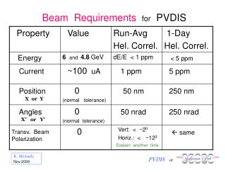
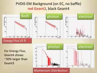
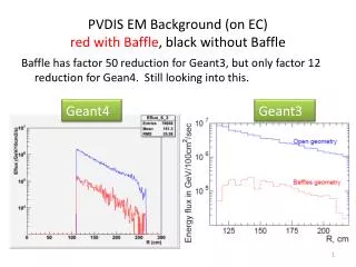
PVDIS baffle Zhiwen Zhao 2013/10/15
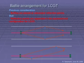
Intro • Previously, I couldn’t obtain an ideal baffle with the code (makebaf5.C) • For the writeup, we used “BaBar more1 block” which is based on Eugene’s BaBar baffle with 5 additional plates and 1 more degree in phi and photon blocks before EC • Now I take a look at baffle design again and try to develop a method
How it’s done, Step 1 • Use CLEO v8 field map • eDIS (W>2) of 40cm long LD2 target, from code eicRate • 11 baffle plates from Z=40cm – 180cm, 30 slits in 1 plate, 20 blocks in 1 slit • 1st baffle min radius at 5cm (>5.2o, to avoid Moller e-) • Study phi change from these eDIS events at every baffle plate front face. Allow 96%(from 2% to 98% of phi change) of rate weighted events with 0.35<x<0.8 and p>1.5GeV to pass through. This define the opening for a very narrow phi slice of eDIS events from the target • Enlarge this opening by 3.5o where positive leaks start to appear, expect 30%=3.5/12 acceptance for eDIS events with 0.35<x<0.8 and p>1.5GeV. I name this “baffle 0.35x3.5deg”
Rate VS Phi turning • 20 blocks at 1st baffle
Rate VS Phi turning • 20 blocks at 11th baffle
“Baffle 0.35x3.5deg” • It looks similar to “BaBar more1”
Acceptance, Baffle 0.35x3.5deg negative source Z(-10,30)cm R(0,3.536)mm for 5x5mm raster neutral positive
How it’s done, Step 2 • Further block photons by adding more material • At the last (11th) baffle, negative and neutral mixes with each other at low phi where high x and high P events are. Block photon here will harm eDIS acceptance at high x. I name this “baffle 0.35x3.5deglast” • At EC, negative and neutral split well from each other due to the additional flight path. Photon block at EC works better. I name this “baffle 0.35x3.5degblock”
Acceptance, Baffle 0.35x3.5degblock negative source Z(-10,30)cm R(0,3.536)mm for 5x5mm raster neutral • EC module R(110,265)cm • EC photon block (“baffle 3.5degblock”) • 30 of them • R(105-200)cm • Start from 3 degree and width 4 degree. (They can be further optimized) • 5cm(8*X0) thick lead, hope to reduce photon energy by 1 order positive
Another adjustment • Optimize for eDIS 0.55<x<0.8 (instead of 0.35<x<0.8) • Enlarge the opening by 5o (instead of 3.5o) where positive leaks start to appear, expect 40%=5/12 (instead of 30%) • Keep all other conditions same
Acceptance, Baffle 0.55x5deg negative source Z(-10,30)cm R(0,3.536)mm for 5x5mm raster neutral positive
Further block photons by adding more material • At the last (11th) baffle, negative and neutral mixes with each other at low phi where high x and high P events are. Block photon here will harm eDIS acceptance at high x • At EC, negative and neutral split well from each other due to the additional flight path. Photon block at EC works better. I name this “baffle 0.55x5degblock”
Acceptance, Baffle 0.55x5degblock negative source Z(-10,30)cm R(0,3.536)mm for 5x5mm raster neutral • EC module R(110,265)cm • EC photon block (“baffle 3.5degblock”) • 30 of them • R(105-205)cm • Start from 2.8 degree and width 4 degree. • 5cm(8*X0) thick lead, hope to reduce photon energy by 1 order positive
eDIS acceptance comparison at EC “0.55x 5deg” and “0.55x 5deg block” has best acceptance at high x
eDISrate comparison at EC “0.55x 5deg” and “0.55x 5deg block” has no low mom leak which could leads to high trig rate
Assume 50uA, 40cm LD2 Pol_beam 85%, 120 days EC R(110,250)cm nominal acceptance Err_Apv(%) No trig cut
For eDIS x>0.8 • For eDIS with cut W>2GeV, events with x>0.8 only happen for large angle • The acceptance shown has cut 22<theta<35deg • There are some acceptance for 35<theta<40deg from the downstream part of the target, but its x only extends to 0.81 (see next slide) • The largest x output by the generator with cut W>2GeV is at 0.84 (see slide after next)
eDIS rate comparison from generator • Red with theta 22-35 deg, blue with theta 22-40 deg
eDIS rate comparison from generator • Red with theta 22-35 deg, blue with theta 0-180 deg