Geotechnical Site Characterization by Cone Penetration Testing
460 likes | 1.94k Vues
Mid-America Earthquake Center. Geotechnical Site Characterization by Cone Penetration Testing. Paul W. Mayne, PhD, P.E. Professor, Geosystems Civil & Environmental Engineering. FHWA. Standard Penetration Test. Rotary-drilled Borehole. Standard Penetration Test (SPT)

Geotechnical Site Characterization by Cone Penetration Testing
E N D
Presentation Transcript
Mid-America Earthquake Center Geotechnical Site Characterization by Cone Penetration Testing Paul W. Mayne, PhD, P.E. Professor, Geosystems Civil & Environmental Engineering FHWA
Standard Penetration Test Rotary-drilled Borehole Standard Penetration Test (SPT) Procedures: ASTM D 1586 N = measured Number of Blows to drive sampler 300 mm into soil.
Effect Variable Term Value Overburden Stress svo' CN (Pa/svo')0.5 but < 2 Energy Ratio1 · Safety Hammer · Donut Hammer · Automatic Hammer CE 0.6 to 0.85 0.3 to 0.6 0.85 to 1.0 Borehole Diameter · 65 to 115 mm · 150 mm · 200 mm CB 1.00 1.05 1.15 Sampling Method · Standard sampler · Sampler without liner CS 1.0 1.1 to 1.3 Rod Length · 10 m to 30 m · 6 to 10 m · 4 to 6 m · 3 to 4 m CR 1.0 0.95 0.85 0.75 Particle Size Median Grain Size (D50) of Sand in mm CP 60 + 25 log D50 Aging Time (t) in years since deposition CA 1.2 + 0.05 log (t/100) Overconsolidation OCR COCR OCR0.2 Corrections to SPT N-value 1 Obtain by energy measurement per ASTM D4633
Corrections to SPT N-value • Nmeasured = Raw SPT Resistance (ASTM D 1586). • N60 = (ER/60) Nmeasured = Energy-Corrected N Value where ER = energy ratio (ASTM D 4633). Note: 30% < ER < 100% with average ER = 60% in the U.S. • N60 CE CB CS CR Nmeas = Estimated corrected N • (N1)60 = CN N60 = Energy-Corrected SPT Value normalized to an effective overburden stress of one atmosphere: (N1)60 = (N60)/(vo’)0.5 with stress given in atm. (Note: 1 atm = 1 bar = 100 kPa = 1 tsf).
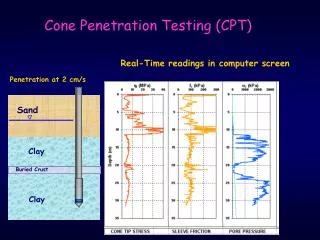
Cone Penetrometers • Electronic Steel Probes with 60° Apex Tip • ASTM D 5778 Procedures • Hydraulic Push at 20 mm/s • No Boring, No Samples, No Cuttings, No Spoil • Continuous readings of stress, friction, pressure
Cone Penetration Tests (CPT) Cone Trucks Mobile 25-tonne rigs with enclosed cabins to allow testing under all weather conditions
Corrections to CPT • Tip Stress correction for porewater pressures on unequal areas – Important in Intact Clays & Silts • Sleeve Friction correction for porewater pressures – Use equal end areas on friction sleeve • Baseline corrections – Obtain before & after sounding
Anchored Cone Rig Mud Island, Downtown Memphis, TN • 6-tonne Geostar truck with 20-tonne hydraulic pushing system • No special license • Twin earth anchors • Has penetrated to depths over 32+ meters at sites in SC, AL, MO, TN, & AL
CPT Profile, Downhole Memphis fs ub qt
Seismic Piezocone Test Vs fs u2 u1 qc Obtains Four Independent Measurements with Depth: • Cone Tip Stress, qt • Penetration Porewater Pressure, u • Sleeve Friction, fs • Arrival Time of Downhole Shear • Wave, ts 60o
Downhole Shear Wave Velocity • Anchoring System • Automated Source • Polarized Wave • Downhole Vs
Automated Seismic Source • Electronically-actuated • Self-contained • Left and right polarization • Modified beam uses fin to enhance shear wave generation • Successfully tested to depths of 20m • Capable of being used with traditional impulse hammer
Downhole Shear Waves Left Strike Right Strike CROSSOVER Method Shear Wave at 8.15 m Shear Wave at 9.20 m CROSSCORRELATION Maximum crosscorrelation at Dt = 6.75 ms Shear wave velocity = 155 m/s Time shift (ms)
CPT Soil Behavioral Classification Soil Behavior Type (Robertson et al., 1986; Robertson & Campanella, 1988) 1 – Sensitive fine grained 5 – Clayey silt to silty clay 9 – sand 2 – Organic material 6 – Sandy silt to silty sand 10 – Gravelly sand to sand 3 – Clay 7 – Silty sand to sandy silt 11 – Very stiff fine grained* 4 – Silty clay to clay 8 – Sand to silty sand 12 – Sand to clayey sand* *Note: Overconsolidated or cemented
CPT-Related Websites • The Liquefaction Site (and CPT site):www.liquefaction.com • Link page to manufacturers, suppliers, and CPT services:http://www.usucger.org/insitulinks.html • Listing of available videos on CPT and other in-situ tests: http://www.geoinstitute.org/in-situ.html • The book Cone Penetration Testing in Geotechnical Practice (Lunne, Robertson, & Powell, 1997): • Review: http://geotech.civen.okstate.edu/magazine/books/ • Order: http://www.routledge-ny.com/