Cryptography Enabled RFID and NVRAM
Cryptography Enabled RFID and NVRAM. Sudhanshu Khanna Ben Calhoun RLP VLSI Group, University of Virginia. Outline. Privacy and Security threats of RFIDs Technical Challenges in implementing cryptography in RFIDs Proposed Solutions: NVRAM is key Chip plans. RFIDs: Widespread and Ubiquitous.

Cryptography Enabled RFID and NVRAM
E N D
Presentation Transcript
Cryptography Enabled RFID and NVRAM Sudhanshu Khanna Ben Calhoun RLP VLSI Group, University of Virginia
Outline • Privacy and Security threats of RFIDs • Technical Challenges in implementing cryptography in RFIDs • Proposed Solutions: NVRAM is key • Chip plans
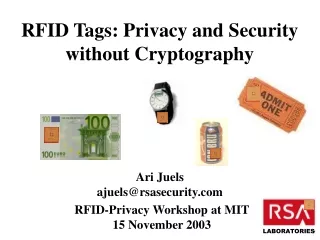
RFIDs: Widespread and Ubiquitous • Supply Chain Management & Retail • Wal-Mart, Gillette, Benetton • Wireless Payment Systems • EZ-Pass, Speedpass • Building Access Cards, Car Keyless Entry
Privacy & Security Concerns • Tags respond to any reader that queries them • Tags can be queried wirelessly • Tags maintain no record of being queried • Users often don’t know they are using RFID
Adversary Models • Corporate Espionage: • Gather competitors supply chain data, inventory status • Gain access to customer preferences/patterns without their consent • Wiping out inventory data • Denial of service by spamming RF
Adversary Models • Personal Privacy Threats: • Tracking an individual using knowledge of the RFID he holds. E.g. People have shown how to track anyone using Nike+, which uses an active RFID tag. • Leaking of personal information. E.g. Prescriptions • Finding individuals who hold some (valuable) item based on the items RFID tag • Cloning a EZ-pass or Building access card
Existing Privacy Features on Tags • Kill command • E.g. Kill a tag on checkout • But you can’t use the tag anymore…. E.g. your “smart-refrigerator” wont be able to detect that your milk is too old • Passwords • Tag only responds to a reader that gives the correct password • Thus, if all tags use same password, the system becomes to vulnerable. Alternatively use per-tag password • Need to maintain extensive tag-password binding
Implementation Challenge • Main security challenges come from resource constraints. • EPC tags ~ 5 cents. • Gate count, memory, power, performance, die space, are all tightly constrained • Encryption solution should add only a fraction to above resources !
Example Tag 0.5mm2 Tag: Digital ~ 30% EEPROM ~ 20% RF + DC reg ~ 20% Others (RNG, Charge Pump, support functions): 30% Barnet et al, “A Passive UHF RFID transponder for EPC Gen2 in 0.13um CMOS” (TI’s gen2 tag) ISSCC 2007
Existing Encryption Solutions • Private Key Schemes not secure: • Break a tag, break the system • Having per tag key results in key-database maintenance issue • Public Key Schemes: • Standard algorithms like RSA are way too expensive • Alternative weaker algorithms like ECC, NTRU, or XTR are also too expensive • Most schemes are not scalable…. Security decreases dramatically with key size (and thus resources)
Proposed Solution: Scalable Security • Key Size determines power, performance • Each Tag has unique small private key • Reader can decryption all tags using same large private key that reader holds • Reader doesn’t need to maintain tag-private key binding • Ease of breaking a tag depends on tag key size • But even if you break a tag, it doesn’t give you any clue on how to break the next… thus the system remains secure
Proposed Solution & CBRAM • This scheme was chosen because its heavily dependent on memory, and memory gives denser implementation than logic-centric schemes • Key is unique to each tag • ROM can’t be used • Solution is NVRAM, or OTP • NVRAM dominates both performance, power, and area • Unique opportunity to leverage CBRAM advantages • CBRAM crucial in making the Encryption scheme feasible
What goes on the ADESTO chip • CBRAM Macro • 64Kb – 128Kb • Sub-VT • Power, Perf, Area all constrained • VCO • Random Number Generator • Random Logic • Arithmetic Logic: adders • Total Area ~ 0.2mm2 (~40K gates)
Block diagram • Pins: • Data (8) • Address (14) • Rd, ER, PR, EDO, EDI • Ext_RNG (8 bit) • Start_enc • Done_enc • Scan_In • Scan_Out • Ciphertext (serial out) • Clock • Supplies: • Array • Periphery • RNG • Adders • Control • VCO Control • Others • VSS Data_In, Addr RD, ER, PR, EDO, EDI Scan_In, Scan_Out NV-RAM 64kb – 128kb RNG EDO, EDI, RD, Addr External RNG Start_Enc Control Adders Done_Enc Ciphertext Clock Output Control Voltage VCO
Detailed Block Diagram Snan_in Settings Snan_in Addr Scan Reg Scan Reg Static Settings Ext Addr Clk RNG Enable Encryption Logic Various internal signals Ext Clk Out Mux RNG Clock Block Out0-4 Clk Static Settings S0-S3 Data, Addr Ext Addr, Data Addr Logic-Mem Interface Data Clk Ext RNG Memory Static Settings RNG Static Settings RNG Block Ext clocks Addr RNG Enable
Goals and Papers • Memory • Energy reduction • Performance (SA) • Impact of variation • VCO • ULP, Low phase noise, jitter, drift • RNG • Logic • Hold time solution
Timeline • May 1st: Tapeout • April: Layout, P&R • March: Schematic, RTL Design, Ideas • Feb: Generating ideas
Memory Size • Total number of rows not fixed • Number of rows vary from 256-1024 • Data width simultaneously varies from 14-56 bits • Block size simultaneously varies from 12 to 3 • Unused blocks may have capability of being switched off
NVRAM Energy-Delay vs. Supply Voltage • What are the most appropriate voltages (VDD, VCC) to read, program, erase? • Setup: • All analysis done using 64kb BLS simulation model • No variation in transistor or PMC parameters • At all VDD, VCC, the RP and ER pulse widths are set such that PMC RLOW and RHIGH are the same
Read Energy-Delay vs. VDD • VDD is the common periphery supply, going everywhere except the bit-lines during PR, ER • Setup: • RD (1) – PR – RD (0) sequence is used and read delay and energy are measured. It is ensured that the RD after PR gives ~15% VDD • Sweep VDD with WL voltage kept at: • VDD for RD • Constant 0.4V for PR • VCC is kept constant at 0.6V for PR
Read Energy-Delay vs. VDD • Read (1) Energy is capacitive in nature, thus its increase with VDD is clear • Read (0) Energy components are partly capacitive and partly due to the static current draw between SA Rpull-up and PMC. As VDD increases, both Rpull-up and access transistor become stronger, and static current rises. Simultaneously pulse width becomes smaller. But power increases faster because VDD is increasing too. Overall, energy increases with VDD
Erase Energy-Delay vs. VCC • Erase pulse width irrelevant because most of the current dies out once the cell is successfully erased • As VCC increases, erase time drops exponentially but current increases only super-linearly as RLOW is constant across VCC • As VCC increases further, capacitive energy starts dominating, and energy starts increasing
Program Energy-Delay vs. VCC • Program pulse width is kept at 2x the program time (to take into account any variation) • As VCC increases, program time drops exponentially but current increases only super-linearly as RLOW is constant across VCC • Most of the energy is consumed after the cell is already written, during the 2x timing margin, which makes program different from erase
Questions • Theoretically explain the components of rd pr er energies • Specifically: • Where is the read 1 energy going?? • Why is program delay decreasing sl slowly with VDD??