Download
1 / 2
20 likes | 47 Vues
The "KEI Ind. Control Cables Product Catalogue" provides comprehensive information about PVC insulated, armoured control cables with special properties to meeting your requirement.

E N D
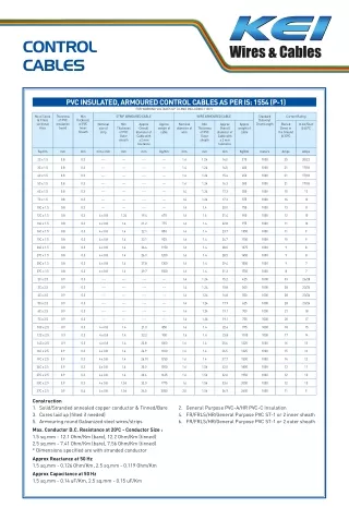
CONTROL CABLES PVC INSULATED, ARMOURED CONTROL CABLES AS PER IS: 1554 (P-1) FOR WORKING VOLTAGES UP TO AND INCLUDING 1100 V No of Cores & Cross sectional Area Thickness of PVC Insulation (nom) Min STRIP ARMOURED CABLE WIRE ARMOURED CABLE Standard Delivery/ DrumLength Current Rating thickness of PVC Inner Sheath Nominal size of strip Min Approx Overall diameter of Cable with ± 2 mm tolerance Approx weight of cable Nominal diameter of wire Min Approx Overall diameter of Cable with ± 2 mm tolerance Approx weight of cable Buried Direct in the Ground @ 30°C In Air/Duct @ 40°C Thickness of PVC Outer sheath Thickness of PVC Outer sheath Sq.mm mm mm mm x mm mm mm Kg/Km mm mm mm Kg/Km meters Amps Amps 2C x 1.5 0.8 0.3 --- --- --- --- 1.4 1.24 14.0 375 1000 25 20/22 3C x 1.5 0.8 0.3 --- --- --- --- 1.4 1.24 14.5 400 1000 21 17/18 4C x 1.5 0.8 0.3 --- --- --- --- 1.4 1.24 15.4 450 1000 21 17/18 5C x 1.5 0.8 0.3 --- --- --- --- 1.4 1.24 16.3 500 1000 21 17/18 6C x 1.5 0.8 0.3 --- --- --- --- 1.4 1.24 17.3 550 1000 15 13 7C x 1.5 0.8 0.3 --- --- --- --- 1.4 1.24 17.3 575 1000 14 13 10C x 1.5 0.8 0.3 --- --- --- --- 1.4 1.4 20.0 750 1000 13 11 12C x 1.5 0.8 0.3 4 x 0.8 1.24 19.4 675 1.6 1.4 21.4 900 1000 12 10 14C x 1.5 0.8 0.3 4 x 0.8 1.4 21.2 775 1.6 1.4 22.8 975 1000 11 10 16C x 1.5 0.8 0.3 4 x 0.8 1.4 22.1 850 1.6 1.4 23.7 1050 1000 11 9 19C x 1.5 0.8 0.3 4 x 0.8 1.4 23.1 925 1.6 1.4 24.7 1150 1000 10 9 24C x 1.5 0.8 0.3 4 x 0.8 1.4 26.4 1150 1.6 1.4 28.0 1375 1000 9 8 27C x 1.5 0.8 0.3 4 x 0.8 1.4 26.9 1200 1.6 1.4 28.5 1450 1000 9 8 30C x 1.5 0.8 0.3 4 x 0.8 1.4 27.8 1300 1.6 1.4 29.4 1550 1000 9 7 37C x 1.5 0.8 0.3 4 x 0.8 1.4 29.7 1500 1.6 1.4 31.3 1750 1000 8 7 2C x 2.5 0.9 0.3 --- --- --- --- 1.4 1.24 15.2 425 1000 33 26/28 3C x 2.5 0.9 0.3 --- --- --- --- 1.4 1.24 15.8 500 1000 28 23/24 4C x 2.5 0.9 0.3 --- --- --- --- 1.4 1.24 16.8 550 1000 28 23/24 5C x 2.5 0.9 0.3 --- --- --- --- 1.4 1.24 17.9 625 1000 28 23/24 6C x 2.5 0.9 0.3 --- --- --- --- 1.4 1.24 19.1 700 1000 21 18 7C x 2.5 0.9 0.3 --- --- --- --- 1.4 1.24 19.1 725 1000 20 17 10C x 2.5 0.9 0.3 4 x 0.8 1.4 21.0 850 1.6 1.4 22.6 975 1000 18 15 12C x 2.5 0.9 0.3 4 x 0.8 1.4 22.2 900 1.6 1.4 23.8 1100 1000 17 14 23.8 1000 1.6 1.4 25.4 1225 1000 16 13 14C x 2.5 0.9 0.3 4 x 0.8 1.4 16C x 2.5 0.9 0.3 4 x 0.8 1.4 24.9 1100 1.6 1.4 26.5 1325 1000 15 13 19C x 2.5 0.9 0.3 4 x 0.8 1.4 26.10 1250 1.6 1.4 27.7 1500 1000 14 12 24C x 2.5 0.9 0.3 4 x 0.8 1.4 30.0 1500 1.6 1.56 32.0 1800 1000 13 11 27C x 2.5 0.9 0.3 4 x 0.8 1.4 30.6 1625 1.6 1.56 32.6 1950 1000 12 10 30C x 2.5 0.9 0.3 4 x 0.8 1.56 32.0 1775 1.6 1.56 33.6 2050 1000 12 10 37C x 2.5 0.9 0.4 4 x 0.8 1.56 34.5 2050 2.0 1.56 36.9 2600 1000 11 9 Construction 1. Solid/Stranded annealed copper conductor & Tinned/Bare 3. Cores laid up (filled if needed) 5. Armouring round Galvanized steel wires/strips Max. Conductor D.C. Resistance at 200C - Conductor Size : 1.5 sq.mm - 12.1 Ohm/Km (bare), 12.2 Ohm/Km (tinned) 2.5 sq.mm - 7.41 Ohm/Km (bare), 7.56 Ohm/Km (tinned) * Dimensions specified are with stranded conductor Approx Reactance at 50 Hz 1.5 sq.mm - 0.126 Ohm/Km, 2.5 sq.mm - 0.119 Ohm/Km Approx Capacitance at 50 Hz 1.5 sq.mm - 0.14 uF/Km, 2.5 sq.mm - 0.15 uF/Km 2. General Purpose PVC-A/HR PVC-C Insulation 4. FR/FRLS/HR/General Purpose PVC ST-1 or 2 inner sheath 6. FR/FRLS/HR/General Purpose PVC ST-1 or 2 outer sheath
CONTROL CABLES PVC INSULATED, UNARMOURED CONTROL CABLES AS PER IS: 1554 (P-1) FOR WORKING VOLTAGES UP TO AND INCLUDING 1100 V No of Cores & Cross sectional Area Thickness of PVC Insulation (nom) Min thickness of PVC Inner Sheath Nom. Thickness of PVC Outer Sheath Approx Overall diameter of Cable with ± 2 mm tolerance mm Approx weight of cable Standard Delivery/ Drum length Current Rating Buried Direct in the Ground @ 30°C Amps In Air/Duct @ 40°C Sq.mm mm mm mm Kg/Km meters Amps 2C x 1.5 0.8 0.3 1.8 12.2 150 1000 25 20/22 3C x 1.5 0.8 0.3 1.8 12.7 175 1000 21 17/18 4C x 1.5 0.8 0.3 1.8 13.6 200 1000 21 17/18 5C x 1.5 0.8 0.3 1.8 14.5 250 1000 21 17/18 6C x 1.5 0.8 0.3 1.8 15.5 275 1000 15 13 7C x 1.5 0.8 0.3 1.8 15.5 300 1000 14 13 10C x 1.5 0.8 0.3 1.8 17.8 400 1000 13 11 12C x 1.5 0.8 0.3 1.8 18.8 450 1000 12 10 14C x 1.5 0.8 0.3 1.8 20.2 500 1000 11 10 16C x 1.5 0.8 0.3 1.8 21.1 560 1000 11 9 19C x 1.5 0.8 0.3 2.0 22.5 660 1000 10 9 24C x 1.5 0.8 0.3 2.0 25.8 800 1000 9 8 27C x 1.5 0.8 0.3 2.0 26.3 875 1000 9 8 30C x 1.5 0.8 0.3 2.0 27.2 950 1000 9 7 37C x 1.5 0.8 0.3 2.0 29.1 1125 1000 8 7 2C x 2.5 0.9 0.3 1.8 13.4 200 1000 33 26/28 3C x 2.5 0.9 0.3 1.8 14.0 225 1000 28 23/24 4C x 2.5 0.9 0.3 1.8 15.0 275 1000 28 23/24 5C x 2.5 0.9 0.3 1.8 16.1 325 1000 28 23/24 6C x 2.5 0.9 0.3 1.8 17.3 375 1000 21 18 7C x 2.5 0.9 0.3 1.8 17.3 400 1000 20 17 10C x 2.5 0.9 0.3 1.8 20.0 550 1000 18 15 12C x 2.5 0.9 0.3 2.0 21.6 650 1000 17 14 14C x 2.5 0.9 0.3 2.0 23.2 725 1000 16 13 16C x 2.5 0.9 0.3 2.0 24.3 800 1000 15 13 19C x 2.5 0.9 0.3 2.0 25.5 900 1000 14 12 24C x 2.5 0.9 0.3 2.0 29.4 1125 1000 13 11 27C x 2.5 0.9 0.3 2.0 30.0 1225 1000 12 10 30C x 2.5 0.9 0.3 2.0 31.0 1350 1000 12 10 37C x 2.5 0.9 0.4 2.2 33.9 1600 1000 11 9 Construction 1. Solid/Stranded annealed copper conductor & Tinned/Bare 2. General Purpose PVC-A/HR PVC-C Insulation 3. Cores laid up (filled if needed) 4. FR/FRLS/HR/General Purpose PVC ST-1 or 2 inner sheath 5. FR/FRLS/HR/General Purpose PVC ST-1 or 2outer sheath Max. Conductor D.C Resistance at 200C - Conductor Size : 1.5 sq.mm - 12.1 Ohm/Km (bare), 12.2 Ohm/Km (tinned) 2.5 sq.mm - 7.41 Ohm/Km (bare), 7.56 Ohm/Km (tinned) * Dimensions specified are with stranded conductor. Approx Reactance at 50 Hz 1.5 sq.mm - 0.126 Ohm/Km, 2.5 sq.mm - 0.119 Ohm/Km Approx Capacitance at 50 Hz 1.5 sq.mm - 0.14 uF/Km, 2.5 sq.mm - 0.15 uF/Km