Download

1 / 18
210 likes | 430 Vues
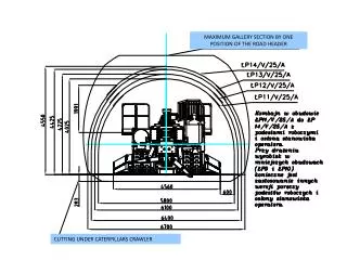
MAXIMUM GALLERY SECTION BY ONE POSITION OF THE ROAD HEADER. CUTTING UNDER CATERPILLARS CRAWLER. REMOVED BARRIERS.

E N D
MAXIMUM GALLERY SECTION BY ONE POSITION OF THE ROAD HEADER CUTTING UNDER CATERPILLARS CRAWLER
Allows heading, crushing, loading cutted rocks, making linning (with telescoping additional arc carrier (boom) jointed to the upper back side and moving platforms jointed on the left and right sides) 1. Gearbox (one or two speed) 2. Cutter head 48 sprayed picks, left 3. Cutter head 48 sprayed picks, right 4. Boom Boom rear pivotal jointed to the turning boom carrier in turntable, moving vertically by two cylinders 200/250kW Cutting motor with hollow shaft and rear elastic clutch No clutch between boom and gearbox Splined shaft connected directly to the bevel spiral pinion in gearbox Gear oil cooler, flow and temperature gauge Gear vibrations gauge Valves to control linning equipment and tools+additional equipment, eg drillers, roofbolters etc. Front lights, methane gauge, frames for spraying water+air system CYLINDER HOLDER TURNTABLE JOINT
Equipment to make linning: Telescoping arc carrier (boom) to carry linning arcs with replaced arc holder Moving platforms, opened outside to make linning/ closed during cutting Removed barriers
LAMPS BOOM LAMPS & CABINE SEARCHLIGHT TELESCOPIC ARC CARRIER PLATFORMS Closed for cutting
TELESCOPIC ARC CARRIER PLATFORMS Closed position for cutting
TURNTABLE Allows moving boom independent vertically and horizontally 1. Boom carrier 2. Body 3. Pivot 4. Turning cylinder Temporary fastening (disconnected unerground) upper plate and pivot. Jointed with expanded pins to frame, rear coupled to transfer cutting force directly to the frame Haulage tunnel between turning cylinders, 800 mm vertical space for conveyor High pressure water pump + motor +valves+hydraulic accumulator inside Rotation gauges (encoders) to controll cutting face shape and anticollision function BOOM PIVOTS BOOM RISING CYLINDERS PIVOTS
GATHERING UNIT Allows loading cutted rocks to the internal chain conveyor 1 Gathering pot 2 Wedge 3 Body 4 Gathering gearbox 5 Pulley 6 Frame / front conveyor 7 Antiwear cover plate 8 Side bracket (pillar) 9 Extension Each gathering gearbox powered by high torque hydraulic motor (3200Nm), one bearing, spur gear, three gaskets sets One type of gearbox on the left and right sides Increased stiffness by side brackets (pillars) connected to the crawler units Different width by replacing extensions Vertically moved by hydraulic cylinders, controlled by rotation gauge (encoder) for antycollision function ROTATION AXLE CYLIDER JOINT
INTERNAL CHAIN CONVEYOR 1. Rear conveyor moving up/down part 2. Front conveyor (in gathering unit) 3. Electric motor 4. Two speed gearbox Powered by two electic 13 KW motors and two-speed gearboxes Chain tension by cylinders filled of grease Max. capacity of conveing rocks 600x700x800 mm Moving catch (hook) cooperating with moving rear conveyor part Rear conveyor and catch moved by hydraulic cylinders FRONT CONVEYOR GATHERING UNIT RISING CYLINDER JOINT FRAME JOINT GEAR CHANGE LEVER
POWERFULL CUTTER TOTAL INSTALLED POWER 390 kW CUTTER MOTOR POWER 200 / 250 kW CUTTING ROCK'S COMPRESSION STRENGHT 110 MPa 3- axle strain gauges clayed in 30 places during cutting tests compared real forces to theoretical stress counting by Von Misses Parrarel paces in 72 MPa concret wall proved good coordination cutter rotation, cutting speed and pick’s pitch
STABILITY LONGITUDINAL STABILITY +/- 18 ˚ TRANSVERSE STABILITY +/- 5˚ GROUND PRESSURE 0,13 MPa
THREE IDEPENDENT SPRAYNG SYSTEMS WATER+PRESSURE AIR SPRAYING SYSTEM water consumption 22 l/min INJECTORY SPRAYING SYSTEM water consumption 27 l/min NOZZLEBEHIND PICKS SYSTEM water consumption 50 l/min
THREE IDEPENDENT SPRAYING SYSTEMS NOZZLEBEHIND PICKS water consumption 50 l/min
SPRAYING SYSTEMS DURING TESTS SPECIAL STAND MAPPING CUTTED ROCK WITH METHANE GAS BLOWING BY SPARKS IN DIFFERENT PLACES WATER + PRESSURE AIR SYSTEM STOPPED THE FLAME, water use: 22 l /min 14
STEERING SYSTEM • CONTROLLING FEATURES: • DIRT LEVEL (CLOG) IN OIL FILTERS IN PRESSURE LINES • TEMPERATURE: PUMPS, CRAWLER + ELECTRIC MOTORS, OIL, CUTTING GEARBOX • STEERING PRESSURE • WATER: FLOW + PRESSURE, AUTOMATIC FILTERS • POSITION EVERY MOVING PARTS – REAR SUPPORTS, PLATFORMS, TELESCOPIC ARC CARRIER, GATHERING UNIT, BOOM • POSTION THE CUTTING HEADS DISPLAYED IN THE CABINE • AIR PRESSURE CONTROLPANEL in machinery cabin PROPORTIONAL ELECTRO-HYDRAULIC STEERING BOOM AND EACH CRAWLER REMOTE CONTROL BASIC STEERING SYSTEM by the radio: 15 m Special additional stand: 50 m
PICKS PACES • PARALLEL LINES AS PICKS TRACES, VISIBLE ZONE OF DEGREASED HORIZONTAL BOOM SPEED, WHEN CUTTING RESISTANCE RISED
K T W - 2 0 0 Total power 390 kW Cutter motor power 200/250 kW Max gallery section 35,5 m2 Compression strenght cutted rock 110 Mpa Voltage 1000 V THE ONLY ONE ROADHEADER WITH LEATHER SEAT