Download

1 / 8
80 likes | 173 Vues
Modification to Allow Automatic Filling of TSI Nephelometer with CO 2. Patrick Sheridan NOAA. Description of the Modification.

E N D
Modification to Allow Automatic Filling of TSI Nephelometer with CO2 Patrick Sheridan NOAA
Description of the Modification The TSI nephelometer can be sent a voltage over the serial port from a computer that will energize the existing BNC connector on the connection plate. We modify the nephelometer so that this voltage is transferred through a newly-installed BNC port to a relay that energizes a solenoid valve that then can let a calibration gas like CO2 pass into the instrument. The procedures we performed to modify the nephelometer are described in the following slides. These include identifying all new components (part numbers and photos), and a basic description of the modifications. Detailed wiring diagrams are not provided in this document, but are available if needed.
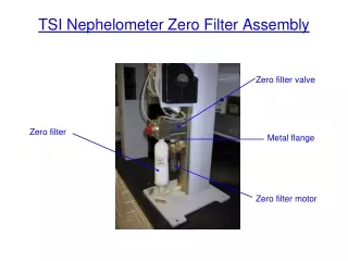
Nephelometer Modifications • The connection plate is modified with a bulkhead tube fitting to permit a ¼-inch tube to be connected to the nephelometer. • Another tube is attached to the back of the connection plate a connected to a solenoid valve assembly on the body of the nephelometer. • A BNC connector is installed on the connection plate to transfer the voltage signal from the existing BNC port to the solenoid relay. • A push button switch is installed to permit manual operation of the CO2 filling operation.
Modification of Connection Plate (1) 3 2 1 • Install ¼-inch Bulkhead Reducer (Swagelok Part# B-400-R1-4, available at www.swagelok.com ). • Install Bulkhead BNC Jack (Digikey Part# ARFX1063-ND, available at www.digikey.com ). • Install Panel-mount Push Button Switch and Protective Cover (Digikey Part# 360-1525 and Part#360-1005-ND, available at www.digikey.com ).
Modification of Connection Plate (2) 3 2 1 • Connect tube from back of bulkhead fitting to solenoid valve inlet. Swagelok elbow union Part# NY-400-9 is required, available at www.swagelok.com • Wire Bulkhead BNC Jack to push button switch. • Wire Panel-mount Push Button Switch to solenoid relay.
CO2 Flow Path 3 2 • CO2 entry point at bulkhead fitting. • CO2 transfer tube. • Solenoid valve that passes CO2 into nephelometer. 1
Solenoid Valve 1 • The solenoid valve is controlled by a MOSFET switch, Part# IPS521S, available at www.irf.com. • The solenoid is Part# ET-2-24-H, available at www.clippard.com. • NOTE: The solenoid used in the modification at WLG does not look like the one in the photo at left. The part# listed above, however, is accurate for the WLG solenoid. The solenoid shown is from an earlier version of the modification.
WLG Solenoid Assembly • The WLG solenoid assembly looks like this. The valve is a cylindrical solenoid. • The MOSFET switch is attached to the metal plate behind the valve. 2 1