Download
1 / 135
2.8k likes | 5.05k Vues
Dynamics of Machinery U5MEA19. Prepared by Mr.Shaik Shabbeer Mr.Vennishmuthu.V Assistant Professor, Mechanical Department VelTech Dr.RR & Dr.SR Technical University. UNIT I : Force Analysis

E N D
Dynamics of MachineryU5MEA19 Preparedby Mr.ShaikShabbeerMr.Vennishmuthu.V Assistant Professor, Mechanical Department VelTech Dr.RR & Dr.SR Technical University
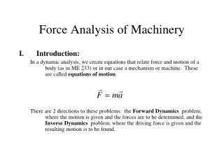
UNIT I : Force Analysis Rigid Body dynamics in general plane motion – Equations of motion - Dynamic force analysis - Inertia force and Inertia torque – D’Alemberts principle - The principle of superposition - Dynamic Analysis in Reciprocating Engines – Gas Forces - Equivalent masses - Bearing loads - Crank shaft Torque - Turning moment diagrams - Fly wheels –Engine shaking Forces - Cam dynamics - Unbalance, Spring, Surge and Windup.
Static force analysis. If components of a machine accelerate, inertia is produced due to their masses. However, the magnitudes of these forces are small compares to the externally applied loads. Hence inertia effect due to masses are neglected. Such an analysis is known as static force analysis • What is inertia? • The property of matter offering resistance to any change of its state of rest or of uniform motion in a straight line is known as inertia.
conditions for a body to be in static and dynamic equilibrium? • Necessary and sufficient conditions for static and dynamic equilibrium are • Vector sum of all forces acting on a body is zero • The vector sum of the moments of all forces acting about any arbitrary point or axis is zero.
Static force analysis and dynamic force analysis. • If components of a machine accelerate, inertia forces are produced due to their masses. If the magnitude of these forces are small compared to the externally applied loads, they can be neglected while analysing the mechanism. Such an analysis is known as static force analysis. • If the inertia effect due to the mass of the component is also considered, it is called dynamic force analysis.
D’Alembert’s principle. • D’Alembert’s principle states that the inertia forces and torques, and the external forces and torques acting on a body together result in statical equilibrium. • In other words, the vector sum of all external forces and inertia forces acting upon a system of rigid bodies is zero. The vector sum of all external moments and inertia torques acting upon a system of rigid bodies is also separately zero.
The principle of super position states that for linear systems the individual responses to several disturbances or driving functions can be superposed on each other to obtain the total response of the system. • The velocity and acceleration of various parts of reciprocating mechanism can be determined , both analytically and graphically.
Dynamic Analysis in Reciprocating Engines-Gas Forces • Piston efforts (Fp): Net force applied on the piston , along the line of stroke In horizontal reciprocating engines.It is also known as effective driving force (or) net load on the gudgeon pin. crank-pin effort. • The component of FQ perpendicular to the crank is known as crank-pin effort. crank effort or turning movement on the crank shaft? • It is the product of the crank-pin effort (FT)and crank pin radius(r).
Forces acting on the connecting rod • Inertia force of the reciprocating parts (F1) acting along the line of stroke. • The side thrust between the cross head and the guide bars acting at right angles to line of stroke. • Weight of the connecting rod. • Inertia force of the connecting rod (FC) • The radial force (FR) parallel to crank and • The tangential force (FT) acting perpendicular to crank
Determination of Equivalent Dynamical System of Two Masses by Graphical Method • Consider a body of mass m, acting at G as • shown in fig 15.15. This mass m, may be replaced • by two masses m1 and m2 so that the system becomes dynamical equivalent. The position of mass m1 may be fixed arbitrarily at A. Now draw perpendicular CG at G, equal in length of the radius of gyration of the body, kG .Then join AC and draw CB perpendicular to AC intersecting AG produced in • B. The point B now fixes the position of the second • mass m2. The triangles ACG and BCG are similar. Therefore,
Turning movement diagram or crank effort diagram? • It is the graphical representation of the turning movement or crank effort for various position of the crank. • In turning moment diagram, the turning movement is taken as the ordinate (Y-axis) and crank angle as abscissa (X axis).
UNIT II : Balancing Static and dynamic balancing - Balancing of rotating masses –Balancing reciprocating masses- Balancing a single cylinder Engine - Balancing Multi-cylinder Engines, Balancing V-engines, - Partial balancing in locomotive Engines-Balancing machines.
STATIC AND DYNAMIC BALANCING When man invented the wheel, he very quickly learnt that if it wasn’t completely round and if it didn’t rotate evenly about it’s central axis, then he had a problem! What the problem he had? The wheel would vibrate causing damage to itself and it’s support mechanism and in severe cases, is unusable. A method had to be found to minimize the problem. The mass had to be evenly distributed about the rotating centerline so that the resultant vibration was at a minimum.
UNBALANCE: The condition which exists in a rotor when vibratory force or motion is imparted to its bearings as a result of centrifugal forces is called unbalance or the uneven distribution of mass about a rotor’s rotating centreline.
BALANCING: Balancing is the technique of correcting or eliminating unwanted inertia forces or moments in rotating or reciprocating masses and is achieved by changing the location of the mass centres. The objectives of balancing an engine are to ensure: 1. That the centre of gravity of the system remains stationery during a complete revolution of the crank shaft and 2. That the couples involved in acceleration of the different moving parts balance each other.
Types of balancing: a) Static Balancing: i) Static balancing is a balance of forces due to action of gravity. ii) A body is said to be in static balance when its centre of gravity is in the axis of rotation. b) Dynamic balancing: i) Dynamic balance is a balance due to the action of inertia forces. ii) A body is said to be in dynamic balance when the resultant moments or couples, which involved in the acceleration of different moving parts is equal to zero. iii) The conditions of dynamic balance are met, the conditions of static balance are also met.
BALANCING OF ROTATING MASSES When a mass moves along a circular path, it experiences a centripetal acceleration and a force is required to produce it. An equal and opposite force called centrifugal force acts radially outwards and is a disturbing force on the axis of rotation. The magnitude of this remains constant but the direction changes with the rotation of the mass.
In a revolving rotor, the centrifugal force remains balanced as long as the centre of the mass of rotor lies on the axis of rotation of the shaft. When this does not happen, there is an eccentricity and an unbalance force is produced. This type of unbalance is common in steam turbine rotors, engine crankshafts, rotors of compressors, centrifugal pumps etc.
The unbalance forces exerted on machine members are time varying, impart vibratory motion and noise, there are human discomfort, performance of the machine deteriorate and detrimental effect on the structural integrity of the machine foundation. Balancing involves redistributing the mass which may be carried out by addition or removal of mass from various machine members. Balancing of rotating masses can be of 1. Balancing of a single rotating mass by a single mass rotating in the same plane. 2. Balancing of a single rotating mass by two masses rotating in different planes. 3. Balancing of several masses rotating in the same plane 4. Balancing of several masses rotating in different planes
BALANCING OF A SINGLE ROTATING MASS BY A SINGLE MASS ROTATING IN THE SAME PLANE Consider a disturbing mass m1 which is attached to a shaft rotating at rad/s.
r = radius of rotation of the mass m The centrifugal force exerted by mass m1 on the shaft is given by, F = m r c 1 1 This force acts radially outwards and produces bending moment on the shaft. In order to counteract the effect of this force Fc1 , a balancing mass m2 may be attached in the same plane of rotation of the disturbing mass m1 such that the centrifugal forces due to the two masses are equal and opposite.
BALANCING OF A SINGLE ROTATING MASS BY TWO MASSES ROTATING There are two possibilities while attaching two balancing masses: 1. The plane of the disturbing mass may be in between the planes of the two balancing masses. 2. The plane of the disturbing mass may be on the left or right side of two planes containing the balancing masses. In order to balance a single rotating mass by two masses rotating in different planes which are parallel to the plane of rotation of the disturbing mass i) the net dynamic force acting on the shaft must be equal to zero, i.e. the centre of the masses of the system must lie on the axis of rotation and this is the condition for static balancing ii) the net couple due to the dynamic forces acting on the shaft must be equal to zero, i.e. the algebraic sum of the moments about any point in the plane must be zero. The conditions i) and ii) together give dynamic balancing.
Problem 1. Four masses A, B, C and D are attached to a shaft and revolve in the same plane. The masses are 12 kg, 10 kg, 18 kg and 15 kg respectively and their radii of rotations are 40 mm, 50 mm, 60 mm and 30 mm. The angular position of the masses B, C and D are 60˚ , 135˚ and 270˚ from mass A. Find the magnitude and position of the balancing mass at a radius of 100 mm. Problem 2: The four masses A, B, C and D are 100 kg, 150 kg, 120 kg and 130 kg attached to a shaft and revolve in the same plane. The corresponding radii of rotations are 22.5 cm, 17.5 cm, 25 cm and 30 cm and the angles measured from A are 45˚, 120˚ and 255˚. Find the position and magnitude of the balancing mass, if the radius of rotation is 60 cm.
UNIT III : Free Vibration Basic features of vibratory systems - idealized models - Basic elements and lumping of parameters - Degrees of freedom - Single degree of freedom - Free vibration - Equations of motion - natural frequency - Types of Damping - Damped vibration critical speeds of simple shaft - Torsional systems; Natural frequency of two and three rotor systems
Introduction • Mechanical vibration is the motion of a particle or body which oscillates about a position of equilibrium. Most vibrations in machines and structures are undesirable due to increased stresses and energy losses. • Time interval required for a system to complete a full cycle of the motion is the period of the vibration. • Number of cycles per unit time defines the frequency of the vibrations. • Maximum displacement of the system from the equilibrium position is the amplitude of the vibration. • When the motion is maintained by the restoring forces only, the vibration is described as free vibration. When a periodic force is applied to the system, the motion is described as forced vibration. • When the frictional dissipation of energy is neglected, the motion is said to be undamped. Actually, all vibrations are damped to some degree.
If a particle is displaced through a distance xm from its equilibrium position and released with no velocity, the particle will undergo simple harmonic motion, • General solution is the sum of two particular solutions, • C1 and C2 are determined by the initial conditions: Free Vibrations of Particles. Simple Harmonic Motion • x is a periodic function and wn is the natural circular frequency of the motion.
amplitude phase angle • Displacement is equivalent to the x component of the sum of two vectorswhich rotate with constant angular velocity period natural frequency Free Vibrations of Particles. Simple Harmonic Motion
Velocity-time and acceleration-time curves can be represented by sine curves of the same period as the displacement-time curve but different phase angles. Free Vibrations of Particles. Simple Harmonic Motion
Consider tangential components of acceleration and force for a simple pendulum, for small angles, Simple Pendulum (Approximate Solution) • Results obtained for the spring-mass system can be applied whenever the resultant force on a particle is proportional to the displacement and directed towards the equilibrium position.
An exact solution for leads to which requires numerical solution. Simple Pendulum (Exact Solution)
Sample Problem • For each spring arrangement, determine the spring constant for a single equivalent spring. • Apply the approximate relations for the harmonic motion of a spring-mass system. A 50-kg block moves between vertical guides as shown. The block is pulled 40mm down from its equilibrium position and released. For each spring arrangement, determine a) the period of the vibration, b) the maximum velocity of the block, and c) the maximum acceleration of the block.
apply the approximate relations for the harmonic motion of a spring-mass system Sample Problem • Springs in parallel: • determine the spring constant for equivalent spring
apply the approximate relations for the harmonic motion of a spring-mass system Sample Problem • Springs in series: • determine the spring constant for equivalent spring
If an equation of motion takes the form the corresponding motion may be considered as simple harmonic motion. • Consider the oscillations of a square plate • For an equivalent simple pendulum, Free Vibrations of Rigid Bodies • Analysis objective is to determine wn.
k Sample Problem • From the kinematics of the system, relate the linear displacement and acceleration to the rotation of the cylinder. • Based on a free-body-diagram equation for the equivalence of the external and effective forces, write the equation of motion. A cylinder of weight W is suspended as shown. Determine the period and natural frequency of vibrations of the cylinder. • Substitute the kinematic relations to arrive at an equation involving only the angular displacement and acceleration.
From the kinematics of the system, relate the linear displacement and acceleration to the rotation of the cylinder. • Based on a free-body-diagram equation for the equivalence of the external and effective forces, write the equation of motion. • Substitute the kinematic relations to arrive at an equation involving only the angular displacement and acceleration. Sample Problem
Sample Problem • Using the free-body-diagram equation for the equivalence of the external and effective moments, write the equation of motion for the disk/gear and wire. • With the natural frequency and moment of inertia for the disk known, calculate the torsional spring constant. The disk and gear undergo torsional vibration with the periods shown. Assume that the moment exerted by the wire is proportional to the twist angle. Determine a) the wire torsional spring constant, b) the centroidal moment of inertia of the gear, and c) the maximum angular velocity of the gear if rotated through 90o and released. • With natural frequency and spring constant known, calculate the moment of inertia for the gear. • Apply the relations for simple harmonic motion to calculate the maximum gear velocity.
Using the free-body-diagram equation for the equivalence of the external and effective moments, write the equation of motion for the disk/gear and wire. • With the natural frequency and moment of inertia for the disk known, calculate the torsional spring constant. Sample Problem
With natural frequency and spring constant known, calculate the moment of inertia for the gear. • Apply the relations for simple harmonic motion to calculate the maximum gear velocity. Sample Problem