ATM Adaptation Layer
This document explores the ATM Adaptation Layer (AAL), detailing its structure including the segmentation and reassembly processes. It describes the two key parts of the Convergence Sublayer: the Service Specific Convergence Sublayer (SSCS) for various services, and the Common Part Convergence Sublayer (CPCS). We analyze the types of AAL, specifically focusing on AAL1 through AAL5, their design for different types of traffic, and their specific applications in connection-oriented and connectionless scenarios. This review highlights the evolution of AAL in supporting various data services, including voice and video.


ATM Adaptation Layer
E N D
Presentation Transcript
ATM Adaptation Layer Raj Jain Professor of Computer and Information ScienceThe Ohio State UniversityColumbus, OH 43210Jain@cse.ohio-State.Edu http://www.cse.ohio-state.edu/~jain/
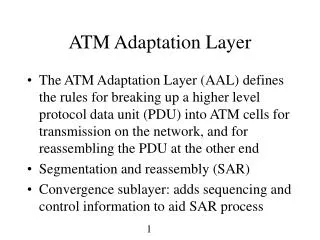
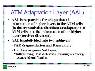
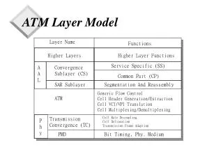
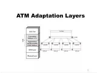
ATM Adaptation Layer • Segmentation and Reassembly • Convergence sublayer: Defines services AAL provides to higher layers. • CS is broken into two parts: • Service Specific Convergence Sublayer (SSCS)Specific to video service, CBR, etc. SSCS of AAL5 is empty. • Common Part Convergence Sublayer (CPCS) ConvergenceSublayer • Service Specific Convergence Sublayer (SSCS) • Common Part Convergence Sublayer (CPCS) Segmentation and Reassembly
Original Classes of Traffic Class A Class B Class C Class D Time Required Not Required Synch Bit Rate Constant Variable Connection Connectionless Connection oriented Mode AAL AAL 1 AAL 2 AAL 3 AAL 4 Examples Circuit Compressed FrameRelay SMDS emulation Video
AAL Types • Initially four classes of AALs. One for each class. • Later four types An AAL type can service more than one class. USA wanted to use one type for both connection-oriented and connectionless data. • AAL type 4 was based on DQDB. • Type 4 could support both Type 3/4 (combined). • AAL type 2 was meant for variable bit rate video. VBR codecs do not exist yet. • AAL 5 Started in ITU. Completed by ATM Forum. • AAL 0 = No AAL = Straight from application to ATM • Signalling AAL (SAAL) uses retransmissions for guaranteed delivery
ConvergenceSublayerIndication SequenceCount SequenceNumber Protection Parity Payload 1b 3b 1b 3b 47B AAL1 Sequence Number • Designed for CBR Traffic • Misordering bad Sequence number • Convergence Sublayer Indication (CSI): Two uses • CSI bits from 4 successive cells = Synchronous Residual timestamp for clock recovery • For structured data transfers: • CSI = 1 8-bit pointer to first byte of payload, 0 no pointer for partially filled cells
AAL Type 2 • Designed for VBR Video/Audio • Under development. One proposal above. • CRC is used for error correction and detection Header Seq # Cell type Payload Length CRC 5B 4b 4b 45B 6b 10b Size
AAL 3/4 • Designed for Data (3 and 4 were merged) • Connectionless or Connection Oriented: • Connectionless PDUs are handled independently • Connection-oriented PDUs may be multiplexed up to 210 logical connections per VC • Message or Streaming Mode: • Message-oriented protocols provide blocks of data • Stream-oriented protocols provide a continuous stream of data presented in fixed size blocks. Blocks may be as small as one byte. One block per cell.
SegmentType Seq No MultiplexingID Payload LengthIndicator CRC AAL 3/4 • Convergence Layer PDU Format CommonPart Indicator Begin Tag BufferAllocationSize Payload PAD Alignment EndTag Len-gth 1B 1B 2B 0-9188B 0-3B 1B 1B 2B • Cell Format 2b 4b 10b 44B 6b 10b
AAL 3/4 • Common Part Indicator (CPI): Interpretation of the PDU. Only one interpretation is currently defined. • Beginning Tag (Btag): PDU sequence number modulo 256 • End Tag (ETag): Must be same as BTag. Ensures the last cell and first cell are from the same PDU. • Buffer Allocation Size: Max buffer size for reassembly. = PDU size for message mode. > Payload size for streaming mode. • Pad: Allows the trailer to begin on a 32-bit boundary • Alignment: Makes the CPCS PDU a multiple of 32-bit • Length: Length of the payload
AAL 5 • Designed for data traffic • Less overhead bits than AAL 3/4 Simple and Efficient AAL (SEAL) • No per cell length field, No per cell CRC UserPayload PAD CommonPartConvergenceSublayer CommonPartIndicator Length CRC-32 0-64kB 0-47B 1B 1B 2B 4B 0 1 AAU bit in PTI indicates last cell
AAL 5 • No per cell overhead. AAL 3/4 uses up 4 bytes per cell for overhead • CPCS User-to-user Indication: Transparently transfer user-to-user information. • Common Part Indicator: Interpretation of the PDU. Only one interpretation is defined. • Higher layers preallocate buffers BAsize is not required • No sequence number Assume ordered delivery • No MID field no PDU multiplexing. End of PDU is marked by AAU bit in the header • No LI field pad is large enough to make PDU a multiple of 48 bytes (rather than 32-bits as in AAL 3/4)
Payload Type Field Coding • 000 User data cell, no congestion, AAU = 0 • 001 User data cell, no congestion, AAU = 1 • 010 User data cell, congestion, AAU = 0 • 011 User data cell, congestion, AAU = 1 • 100 Segment OAM F5 cell • 101 End-to-end OAM F5 cell • 110 Resource management cell • 111 Reserved ATM-user-to-ATM-user (AAU) bit available for user-to-user indication OAM cells may be inserted in any VC In-band signaling
Operation Administration and Maintenance (OA&M) • For supervision, testing, and performance monitoring • Loopbacks for maintenance • ITU TS standard uses CMIP • Organized into 5 hierarchical levels • Virtual Channel (F5) • Virtual Path (F4) • Transmission Path (F3) • Digital Section (F2) • Regenerator Section (F1)
OAM Flows Multiplexor Switch Switch Repeater Repeater TerminatingEquipment TerminatingEquipment Section Section Section Section Line Line Path/Channel F1 F1 F1 F1 F2 F2 F3 F4 F5
OAM Flows • F5: Between VC endpoints • F4: Between VP endpoints • F3: Between elements that perform assembling, disasembling of payload, header, or control • F2: Between section end-points. Performs frame synchronization. • F1: Between regeneration sections.
TerminatingEquipment Switch Switch TerminatingEquipment Segment vs End-to-End Flows • End-to-end flows are seen by the user • Segment flows are not seen by the user • Segment = Single VP/VC link or a group of VP/VC within one network provider • Both types of flows can be VP flows (F4) or VC flows (F5) • F5 flows are identified by PTI = 4 or 5. VPI/VCI same as in user's flow. • F4 flows are identified by VC = 3 or 4. VPI same as in user's flow. End-to-end Segment
Preassigned VPI/VCI Values • 0/0 Unassigned or Idle • 0/1 Metasignaling • 0/3 Segment F4 Flow • 0/4 End-to-end F4 flow • 0/5 Signaling • 0/15 SMDS • 0/16 Interim Layer Management Interface (ILMI)
References • ITU-T Recommendation I.363, “B-ISDN ATM Adaptation Layer (AAL) Specification,” March 1993. • T. Suzuki, "ATM Adaptation Layer Protocol," IEEE Communications Magazine, April 1994.