LAN switching and Bridges
420 likes | 676 Vues
LAN switching and Bridges. CS491G: Computer Networking Lab V. Arun. Slides adapted from Liebeherr and El Zarki , and Kurose and Ross. Outline. Interconnection devices Bridges/LAN switches vs. Routers Bridges Learning Bridges Transparent bridges. Introduction .

LAN switching and Bridges
E N D
Presentation Transcript
LAN switching and Bridges CS491G: Computer Networking Lab V. Arun Slides adapted from Liebeherr and El Zarki, and Kurose and Ross
Outline • Interconnection devices • Bridges/LAN switches vs. Routers • Bridges • Learning Bridges • Transparent bridges
Introduction • Several different devices for interconnecting networks
Ethernet Hub • Connects hosts to Ethernet LAN and connects multiple Ethernet LANs • Collisions are propagated
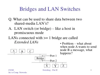
Bridges/LAN switches • A bridgeor LAN switch is a device that interconnects two or more Local Area Networks (LANs) and forwards packets between these networks. • Bridges/LAN switches operate at the Data Link Layer (Layer 2)
Ethernet Hubs vs. Ethernet Switches • An Ethernet switch is a packet switch for Ethernet frames • Buffering of frames prevents collisions. • Each port is isolated and builds its own collision domain • An Ethernet Hub does not perform buffering: • Collisions occur if two frames arrive at the same time. Hub Switch
Dual Speed Ethernet hub • Dual-speed hubs operate at 10 Mbps and 100 Mbps per second • Conceptually these hubs operate like two Ethernet hubs separated by a bridge Dual-Speed Ethernet Hub
Routers • Routers operate at the Network Layer (Layer 3) • Interconnect IP networks
Bridges versus Routers • An enterprise network (e.g., university) with a large number of local area networks (LANs) can use routers or bridges • 1980s: LANs interconnection via bridges • Late 1980s and early 1990s: increasingly use of routers • Since mid1990s: LAN switches replace most routers
Internet A Routed Enterprise Network Router Hub FDDI FDDI
Internet A Switched Enterprise Network Router Bridge/Switch
Routers Each host’s IP address must be configured If network is reconfigured, IP addresses may need to be reassigned Routing done via RIP or OSPF Each router manipulates packet header (e.g., reduces TTL field) Bridges/LAN switches MAC addresses of hosts are hardwired No network configuration needed Routing done by learning bridge algorithm spanning tree algorithm Bridges do not manipulate frames Interconnecting networks: Bridges versus Routers
Bridges Overall design goal: Complete transparency “Plug-and-play” Self-configuring without hardware or software changes Bridges should not impact operation of existing LANs Three parts to understanding bridges: (1) Forwarding of Frames (2) Learning of Addresses (3) Spanning Tree Algorithm
(1) Frame Forwarding • Each bridge maintains a MAC forwarding table • Forwarding table plays the same role as the routing table of an IP router • Entries have the form ( MAC address, port, age), where MAC address:host name or group address port:port number of bridge age:aging time of entry (in seconds) with interpretation: a machine with MAC address lies in direction of the port number from the bridge. The entry is age time units old. MAC forwarding table
(1) Frame Forwarding • Assume a MAC frame arrives on port x. Is MAC address of destination in forwardingtable for ports A, B, or C ? Notfound ? Found? Forward the frame on theappropriate port Flood the frame, i.e., send the frame on all ports except port x.
Src=x, Dest=y Src=x, Dest=y Src=x, Dest=y Src=y, Dest=x Src=x, Dest=y Src=x, Dest=y Src=x, Dest=y Src=x, Dest=y Src=x, Dest=y Src=y, Dest=x (2) Address Learning (Learning Bridges) • Routing entries set automatically with a simple heuristic: Source field of a frame that arrives on a port tells which hosts are reachable from this port. Port 1 Port 4 x is at Port 3 y is at Port 4 Port 2 Port 5 Port 3 Port 6
Src=y, Dest=x Src=y, Dest=x (2) Address Learning (Learning Bridges) Learning Algorithm: • For each frame received, the source stores the source field in the forwarding database together with the port where the frame was received. • All entries are deleted after some time (default is 15 seconds). Port 1 Port 4 x is at Port 3 y is at Port 4 Port 2 Port 5 Port 3 Port 6
Example Consider the following packets: (Src=A, Dest=F), (Src=C, Dest=A), (Src=E, Dest=C) What have the bridges learned?
What do bridges do if some LANs are reachable only in multiple hops ? What do bridges do if the path between two LANs is not unique ? Need for a forwarding between networks
F F F F F F Problems with network of bridges • Consider the two LANs that are connected by two bridges. • Assume host n is transmitting a frame F with unknown destination. What is happening? • Bridges A and B flood the frame to LAN 2. • Bridge B sees F on LAN 2 (with unknown destination), and copies the frame back to LAN 1 • Bridge A does the same. • Duplication causes “broadcast storm” Where’s the problem? What’s the solution ? F
Transparent Bridges • Three principal approaches can be found: • Fixed Routing • Source Routing • Spanning Tree Routing (IEEE 802.1d) • We only discuss the last one • Bridges that execute the spanning tree algorithm are called transparent bridges
Spanning Tree Protocol (IEEE 802.1d) • Spanning Tree Protocol (SPT) is a solution to prevent loops when forwarding frames between LANs • Standardized as IEEE 802.1d • SPT organizes bridges and LANs as spanning tree in a dynamic environment • Frames are forwarded only along the branches of the spanning tree • Trees don’t have loops • Bridges that run SPT are called transparent bridges • Bridges exchange messages to configure the bridge (Bridge Protocol Data Unit or BPDUs) to build tree.
What do the BPDUs do? With the help of the BPDUs, bridges can: • Elect a single bridge as the root bridge. • Calculate the distance of the shortest path to the root bridge • Each LAN can determine a designated bridge, which is the bridge closest to the root. The designated bridge will forward packets towards the root bridge. • Each bridge can determine a root port, the port that gives the best path to the root. • Select ports to be included in the spanning tree.
Concepts • Each bridge as a unique identifier: Bridge ID Bridge ID = Priority : 2 bytes Bridge MAC address: 6 bytes • Priority is configured • Bridge MAC address is lowest MAC addresses of all ports • Each port of a bridge has a unique identifier (port ID). • Root Bridge:The bridge with the lowest identifier is the root of the spanning tree. • Root Port: Each bridge has a root port which identifies the next hop from a bridge to the root.
Concepts • Root Path Cost: For each bridge, the cost of the min-cost path to the root. • Designated Bridge, Designated Port:Single bridge on a LAN that provides the minimal cost path to the root for this LAN: - if two bridges have the same cost, select one with highest priority - if min-cost bridge has two or more ports on the LAN, select port with lowest ID • Note: We assume that “cost” of a path is the number of “hops”.
Steps of Spanning Tree Algorithm • Each bridge is sending out BPDUs that contain the following information: • Transmission of BPDUs results in the distributed computation of a spanning tree • Convergence of the algorithm is very quick root ID cost bridge ID port ID root bridge (what the sender thinks it is) root path cost for sending bridgeIdentifies sending bridgeIdentifies the sending port
Ordering of Messages • We define an ordering of BPDU messages We say M1 advertises a better path than M2 (“M1<<M2”) if (R1 < R2), Or (R1 == R2) and (C1 < C2), Or (R1 == R2) and (C1 == C2) and (B1 < B2), Or (R1 == R2) and (C1 == C2) and (B1 == B2) and (P1 < P2) ID R1 C1 ID B1 ID P1 ID R2 C2 ID B2 ID P2 M1 M2
Initializing the Spanning Tree Protocol • Initially, all bridges assume they are the root bridge. • Each bridge B sends BPDUs of this form on its LANs from each port P: • Each bridge looks at the BPDUs received on all its ports and its own transmitted BPDUs. • Root bridge updated to the smallest received root ID that has been received so far B 0 B P
R1 R2 C1 C2 B1 B2 P1 P2 M1 M2 R2 C2+1 B1 P1 Operations of Spanning Tree Protocol • Each bridge B looks on all its ports for BPDUs that are better than its own BPDUs • Suppose a bridge with BPDU: receives a “better” BPDU: Then it will update the BPDU to: • However, the new BPDU is not necessarily sent out • On each bridge, the port where the “best BPDU” (via relation “<<“) was received is the root port of the bridge.
When to send a BPDU • Say, B has generated a BPDU for each port x • B will send this BPDU on port x only if its BPDU is better (via relation “<<“) than any BPDU that B received from port x. • In this case, B also assumes that it is the designated bridge for the LAN to which the port connects • And port x is the designated port of that LAN R Cost B x
Selecting the Ports for the Spanning Tree • Each bridges makes a local decision which of its ports are part of the spanning tree • Now B can decide which ports are in the spanning tree: • B’s root port is part of the spanning tree • All designated ports are part of the spanning tree • All other ports are not part of the spanning tree • B’s ports that are in the spanning tree will forward packets (=forwarding state) • B’s ports that are not in the spanning tree will not forward packets (=blocking state)
Building the Spanning Tree • Consider the network on the right. • Assume that the bridges have calculated the designated ports (D) and the root ports (R) as indicated. • What is the spanning tree? • On each LAN, connect R ports to the D ports on this LAN
Example • Assume that all bridges send out their BPDU’s once per second, and assume that all bridges send their BPDUs at the same time • Assume that all bridges are turned on simultaneously at time T=0 sec.
Example: BPDU’s sent by the bridges In the table (1,0,1,port) means that the BPDU is (1,0,1,A) if the BPDU is sent on port A and (1,0,1,B) if it is sent on port B. At T=1, Bridge 7 receives two BPDUs from Bridge 1: (1,0,1,A) and (1,0,1,B). We assume that A is numerically smaller than B. If not, then the root port of Bridge 7 changes.
Example: Settings after convergence Resulting tree:
VLANs: motivation consider: • CS user moves office to EE, but wants connect to CS switch? • single broadcast domain: • all layer-2 broadcast traffic (ARP, DHCP, unknown location of destination MAC address) must cross entire LAN • security/privacy, efficiency issues Computer Science Computer Engineering Electrical Engineering Link Layer
7 1 2 8 15 9 10 16 VLANs Virtual Local Area Network port-based VLAN: switch ports grouped (by switch management software) so that singlephysical switch …… 15 7 9 1 2 8 10 16 switch(es) supporting VLAN capabilities can be configured to define multiple virtualLANS over single physical LAN infrastructure. … … Computer Science (VLAN ports 9-15) Electrical Engineering (VLAN ports 1-8) … operates as multiplevirtual switches … … Computer Science (VLAN ports 9-16) Electrical Engineering (VLAN ports 1-8) Link Layer
forwarding between VLANS:done via routing (just as with separate switches) • in practice vendors sell combined switches plus routers Port-based VLAN router • traffic isolation:frames to/from ports 1-8 can only reach ports 1-8 • can also define VLAN based on MAC addresses of endpoints, rather than switch port 15 7 9 1 2 8 10 16 • dynamic membership: ports can be dynamically assigned among VLANs … … Computer Science (VLAN ports 9-15) Electrical Engineering (VLAN ports 1-8) Link Layer
1 16 VLANS spanning multiple switches • trunk port:carries frames between VLANS defined over multiple physical switches • frames forwarded within VLAN between switches can’t be vanilla 802.1 frames (must carry VLAN ID info) • 802.1q protocol adds/removed additional header fields for frames forwarded between trunk ports 15 7 9 7 1 3 5 2 8 10 4 6 2 8 … … Computer Science (VLAN ports 9-15) Ports 2,3,5 belong to EE VLAN Ports 4,6,7,8 belong to CS VLAN Electrical Engineering (VLAN ports 1-8) Link Layer
802.1Q VLAN frame format type source address dest. address preamble data (payload) 802.1 frame CRC type 802.1Q frame data (payload) CRC 2-byte Tag Protocol Identifier (value: 81-00) Recomputed CRC Tag Control Information (12 bit VLAN ID field, 3 bit priority field like IP TOS) source address dest. address preamble Link Layer