Electromagnetic Induction in Physics
Learn about electromagnetic induction, Faraday's laws, Lenz’s law, and applications like electric generators. Discover mutual and self induction, back EMF, and practical insights on how changing magnetic fields induce current.

Electromagnetic Induction in Physics
E N D
Presentation Transcript
Chap 28 Electromagnetic Induction
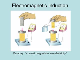
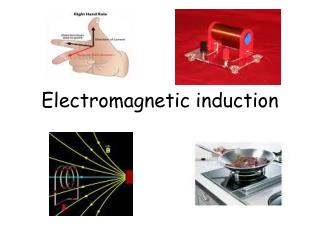
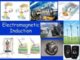
When current passes through a wire it generates a magnetic field. Similarly, if a changing magnetic field passes through a coil, an emf appears in the coil. This phenomenon is called electromagnetic induction
To demonstrate electromagnetic induction (a) coil and magnet (b) coil and coil-one of coils connected to ac supply – changing magnetic field is generated in this coil which then induces a current in the second coil NOTE: The current depends on the fact that the magnetic field is changing . Exp.
Magnetic flux Φ • Magnetic flux can be thought of as the total no. of magnetic field lines passing through a particular area. • Φ = BA • B = magnetic flux density, A = area
Magnetic flux is a scalar quantity Unit = weber (Wb) The magnetic flux is 1 Weber if the magnetic flux density over an area of 1m2 is 1T
When a changing magnetic field is applied to a coil an emf is induced in the coil The size of the induced emf is directly proportional to the rate of change of flux Faraday’s laws of electromagnetic induction
Induced emf = change in flux / time E = (final flux – initial flux) / time E = - dΦ / dt The minus sign indicates the direction of the induced emf, and can be ignored in calculations of E Do questions p315
States that the direction of the induced emf is such as to oppose the motion causing it. E.g. if the current is caused by a north pole approaching the coil, this is the motion the current seeks to oppose→ the current flows in such a direction as to make that end of the coil into a north pole (i.e. opposes the north pole approaching). This means work must be done to push the magnet towards the coil. This loss of energy = gain of electrical energy of the coil Lenz’s Law
If however, the north pole is moving away from the coil, the current flows such that a south pole is created at that end of the coil ( this will attract the north pole back, i.e. oppose the north pole moving away) This is why as the magnet moves in and out the induced current changes direction
If Lenz’s law were not true, then as the north pole approaches, a south pole could be induced. This would attract the magnet even faster, causing a bigger current, causing it to go faster etc. Thus both magnet and coil would gain energy. This energy would be coming from nowhere and so violate the principle of conservation of energy
Electric generator • -converts mechanical energy to electrical energy • Opposite system to dc motor • In this system the coil is turned mechanically in the magnetic field
As the coil turns an emf is produced across the coil, and a current flows. Each ½ cycle the direction of the induced current changes direction, thus generating A.C. If d.c. is required a split ring commutator is used to change the direction every ½ cycle Generators are found in power stations, alternators in cars, dynamo of a bike
Current of 50 Hz means 50 complete cycles per sec. This means the current changes direction 100 times per sec. Alternating current
AC is continuously changing. When values are quoted for a.c. (e.g. 3A a.c.) what it actually means is that this quantity of a.c. generates heat at the same rate as a direct current of 3A would generate AC values
Since a.c. is always changing, when a value of a.c. current is quoted, it must be an average of sorts. The average used is the root mean square value Irms = Io / 2 Vrms = V0 /2 I0 or V0 = maximum values Do questions p321 Measuring ac
If you place 2 coils near each other, a changing magnetic field in one will induce an emf, and hence current in the other. This induced current is a.c. and so induces a changing magnetic field in the second coil. Thus the first coil is now in the changing magnetic field due to the second coil, so an emf is induced in the first coil Mutual induction
When ac flows through a coil, a magnetic field is created around the coil. Thus the coil itself is now sitting in a changing magnetic field, so an emf is induced in the coil. This induced emf opposes the driving emf, according to Lenz’s law. Self induction
The effect of this induced current is to reduce the effective current flowing in the coil. When motors are being made, they take into account that by virtue of the fact that a motor spins, the coil will be in a changing magnetic field, and so there will be an induced back emf. Back EMF
Thus the current which will actually flow through the wire is less than the initial forward current. The coil is manufactured to handle this reduced current. If a motor is not allowed to spin freely, there is no back emf, and so the current then flowing will be bigger than what the coil was manufactured to carry → the coil will burn out
If an inductor (coil) is used in a circuit with an a.c. source, since the current through the coil is always changing, there will always be a back emf and current which will oppose the driving current. • If a soft iron core is inserted in the coil, the induced magnetic field, and hence back emf is greater, so the overall current is even less. a.c. and inductors.
If an induction coil is used with a d.c. source it has no effect (since there is no induced changing magnetic field except for the initial instant while the current is building up to its maximum value)
If a capacitor is used with an a.c. source, the capacitor starts to charge from one side, then when the current changes direction the capacitor empties from that side and starts to charge from the other side. This happens repeatedly so the capacitor never gets fully charged a.c. and capacitors
Since a capacitor only blocks current once it is fully charged, capacitors don’t block a.c In the case of d.c., other than the initial period when the capacitor is charging, capacitors block d.c.
- a device to change the value of an alternating voltage. Consists of 2 coils of wire wound around a soft iron core (to increase the magnetic effect) Transformers
An alternating voltage (Vin) and current is applied to the primary coil. This generates a changing magnetic field around this coil. The nearby secondary coil is now in a changing magnetic field → an induced emf (Vout)and current is generated across the secondary coil.
The relative sizes of the input and output voltages depend on the no. of turns of wire in primary and secondary coils. Vin / Vout = Np / Ns If there are no energy losses in the transformer then power stays the same Pin = Pout
But P = V I Vin Iin = Vout Iout Vin / Vout = Iout / Iin Do questions p327
Used by power stations to minimise heat losses in cables by transforming voltages to very high values. Used in many everyday household electrical items to supply the necessary voltages to various parts Uses of transformers