Download
1 / 18
180 likes | 364 Vues
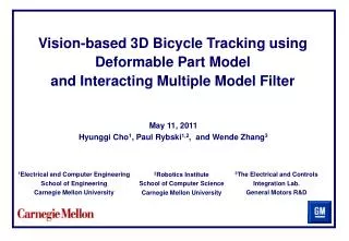
Vision-Based Tracking of a Moving Object by a 2 DOF Helicopter Model: The Simulation. Chayatat Ratanasawanya October 30, 2009. Overview. Classification of visual-servo systems Components of the simulation The non-linear model of the helicopter The LQR controller

E N D
Vision-Based Tracking of a Moving Object by a 2 DOF Helicopter Model: The Simulation ChayatatRatanasawanya October 30, 2009
Overview • Classification of visual-servo systems • Components of the simulation • The non-linear model of the helicopter • The LQR controller • Perspective projection model & camera calibration • Coordinate systems • Determination of the position of the ball • The simulation: logic and result • Summary • Questions/comments
Visual-servo systems taxonomy • In 1980, Sanderson and Weiss introduced a taxonomy of visual servo systems. Two questions: • Is the control structure hierarchical, with the vision system providing set-points as input to the robot’s joint-level controller, or does the visual controller directly compute the joint-level inputs? • Is the error signal defined in 3D (task space) coordinates or directly in terms of image features?
4 system structures Dynamic position-based look-and-move structure Dynamic image-based look-and-move structure
4 system structures Position-based visual servo structure Image-based visual servo structure
The simulation - an introduction • The system being simulated can be categorized as a dynamic position-based look-and-move system. • The non-linear model of the helicopter and the joint-level LQR controller (implemented by Quanser). • Perspective projection model & camera calibration. • Coordinate systems • Determination of the ball’s position in world frame & in camera frame.
The non-linear modelof the helicopter • A block in Simulink provided by Quanser, which captures the dynamic equations of the helicopter plant.
The LQR controller • A controller design technique that works with the state-space representation of a plant/system. with weighting matrices Q and R, calculate • Has the same action as a PD or a PID controller. • In the simulation, it is a joint-level controller.
Perspective projection model &camera calibration • The projection model is used to relate the position of an object in the camera frame to the pixel coordinate of the image of that object on the image plane.
Coordinate systems • The world frame: stationary frame attached to the pivot point. • The helicopter frame: attached to the helicopter at the pivot point. It moves with the helicopter. • The camera frame: attached to the camera at the center of projection. z y x x z z x y y
Determination of the ball’s position:the scenario • Initially a ping-pong ball is right in front of the camera. r1 r3 r2
Determination of the ball’s position:the scenario • The ball is moved to a new position. The helicopter hasn’t moved yet. r3n r1 r2n
Determination of the ball’s position:the scenario • The helicopter moves to the new position to align the ball to the camera. r3n r1 r2ss
Determination of the ball’s position:recap • The ball is initially right in front of the camera. We know the pose of the helicopter (0 and 0). • The ball is moved. Get new ball position in the camera frame from inverse projection model. Use the current pose to calculate new ball position in the world frame. • Use ball position in the world frame from the previous step to calculate the desired pose (d and d). • Pass these values to the LQR controller.
Implementation • The first step towards implementation has been taken; i.e. locating the ball’s centre of gravity in real time.
summary • Visual-servo systems taxonomy • Components of the simulation • The non-linear dynamic model • The controller • Projection model • Coordinate systems • Locating the ball • The simulation • First step towards implementation
Questions/comments 7th annual UVS Canada conference 2009 Victoria, BC. November 2-5, 2009