Download
1 / 88
880 likes | 998 Vues
Discover the flexibility of the InteliGen Hardware Platform, designed to support various applications like AMF, utility paralleling, and multi-set operations. The same controller serves diverse functions, ensuring efficient hardware expansion through added control and interface features tailored to your specific needs. With additional modules such as iG-PCM for governor settings and iG-CUa for comprehensive control interfaces, InteliGen provides a reliable solution for power management and system coordination in varied environments.

E N D
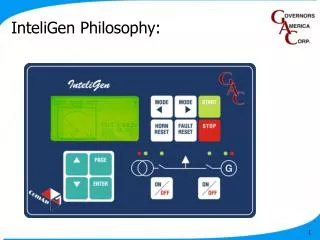
IG Philosophy Title InteliGen Philosophy:
Common Hardware Platform InteliGen Philosophy: Common Hardware Platform The same controller used for different applications, e.g. AMF, paralleling to the utility, multi-set paralleling.
Hardware Expansion Modules InteliGen Philosophy: Common Hardware Platform The same controller used for different applications, e.g. AMF, paralleling to the utility, multi-set paralleling. Hardware Expansion Modules Extra control and interface features added according to application.
Expansion: PCM InteliGen Philosophy: Common Hardware Platform The same controller used for different applications, e.g. AMF, paralleling to the utility, multi-set paralleling. Hardware Expansion Modules Extra control and interface features added according to application. iG-PCM: Governor & AVR interface for single set utility paralleling. iG-CUa
Expansion: PCLSM+COM InteliGen Philosophy: Common Hardware Platform The same controller used for different applications, e.g. AMF, paralleling to the utility, multi-set paralleling. Hardware Expansion Modules Extra control and interface features added according to application. iG-PCLSM+iG-COM: Governor, AVR, Load share and CAN communications interface for multi-set paralleling, or multi-set paralleling to the utility. iG-CUa
Software Applications InteliGen Philosophy: Common Hardware Platform The same controller used for different applications, e.g. AMF, paralleling to the utility, multi-set paralleling. Hardware Expansion Modules Extra control and interface features added according to application. Different Software Applications A configuration file defines which functions and setpoints are active, as well as defining the sequence and conditions for control events.
DC Power IG-CUa: External Connections DC Power 8-36V range. When the supply voltage drops below 8 volts, display backlight switches off.
12v systems IG-CUa: External Connections DC Power 8-36V range. When the supply voltage drops below 8 volts, display backlight switches off.
Starter Volt Drop IG-CUa: External Connections DC Power 8-32V range. When the supply voltage drops below 8 volts, display backlight switches off. To help minimise voltage drop on cranking, connect IG DC supply to battery terminals through a fusible link, do not connect directly to starter motor. IG-CUa Starter
Gen Volts IG-CUa: External Connections Generator Voltage Direct Connection up to 480 VAC, P.T. ratios for higher voltages. Minimum 80v, maximum 347v (L-N). Above 347 VAC, accuracy decreases due to clipping of A-D converter. Phase rotation checked by IG-CUa
Mains/Bus volts IG-CUa: External Connections Utility/Bus Voltage Same input range as Generator Volts If Utility input terminals are not used, for example Single set Prime Mover application, short L1,L2, and L3 to N. If 4 pole breakers are used, or the system is 3 wire only, use IG-MTU.
MTU IG-CUa: External Connections Utility or Bus Generator
Single Phase IG-CUa: External Connections Single Phase connection Connect L1 and L3, tie L2 to N. IG-CUa automatically detects single phase application and protects on only line 1 and 3. If neutral is not solid, i.e. two pole switches, isolation transformer must be used e.g. IG-TRANS.
Gen CT IG-CUa: External Connections Generator CT Inputs 5A Secondary. The current inputs are isolated, therfore the CT’s can be placed anywhere in CT measuring circuit(e.g. other metering can be done before the IG.) L1k (S1) should point to alternator, L1l (S2) should point to load. CT phasing can be checked during test/commissioning by looking at kw meter page. CT input burden <0.2VA per phase.
Neutral CT IG-CUa: External Connections Neutral/Utility In CT Input Inl, Ink terminals are for neutral CT Separate ratio and protection settings. Can be used for neutral current or ground fault measurement. In Single Set Parallel to Utility application, In must be used for Utility current measurement (L3).
Earth Fault IG-CUa: External Connections Ground Fault, all zones. Unrestricted Ground Fault Restricted Ground Fault
Mains CT IG-CUa: External Connections Ink/Inl used for Neutral metering Ink/Inl must be used for Utility L3 current when using Single set Parallel to Utility application.
Binary Inputs IG-CUa: External Connections Binary Inputs 9 Inputs on IG-CUa. Configurable using WinEdit: function, NO/NC etc. When input is active, it will be closed to ground. iG-CUa
Binary Outputs IG-CUa: External Connections 9 Outputs on IG-CUa. Configurable using WinEdit. BO1 and BO2 are relay outputs, N/O contact. Rating 12A resistive, 4A inductive. BO3-BO9 open collector, rating 0.5A. When outputs are active, they close to ground (open collector). For the two relays, they simply close (BO1, BO2) Diode placement is recommended on BO3-BO9. Binary Outputs iG-CUa
Analogue Inputs IG-CUa: External Connections Analog Inputs 3 Analog sender Inputs. Resistance range 0-2.4k Ohms. Three configurable analog curves as well as predefined VDO curves, 2 stage (warning and shutdown) protection on analog inputs 1 and 3. Three level (low temp warning) on analog input 2.
4-20mA + Tri-state IG-CUa: External Connections iG-CUa iG-CUa iG-CUa Normal Connection. Resistive senders. 4-20mA senders. 0-60 or 0-100 range curves available. Accuracy using current senders is reduced by 50%. Binary and Tri-State switch input.
RPM input IG-CUa: External Connections RPM Input Min pick-up requirements 2v (p-p) from 4-4kHz. 4khz to 10kHz min pick volt increases to 6v (p-p) The mag pick-up should be connected to the controller via a shielded cable. Connect the shielding wire to ground screw. Sometimes sharing one mag pick-up between the controller and governor can cause system problems. If a mag pick-up is not used, RPM will calculate speed on frequency.
Earth Screws IG-CUa: External Connections Ground Connections At least one ground screw should be connected to the panel or panel ground.
Operator interface IG-CUa: Operator Interface Control Pushbuttons
MODE < IG-CUa: Operator Interface Control Pushbuttons MODE < : change operating mode from MAN to OFF, AUT to MAN etc
MODE > IG-CUa: Operator Interface Control Pushbuttons MODE < : change operating mode from MAN to OFF, AUT to MAN etc MODE > : change operating mode from OFF to MAN, MAN to AUT etc
HORN RESET IG-CUa: Operator Interface Control Pushbuttons MODE < : change operating mode from MAN to OFF, AUT to MAN etc MODE > : change operating mode from OFF to MAN, MAN to AUT etc HORN RESET : silence horn output
FAULT RESET IG-CUa: Operator Interface Control Pushbuttons MODE < : change operating mode from MAN to OFF, AUT to MAN etc MODE > : change operating mode from OFF to MAN, MAN to AUT etc HORN RESET : silence horn output FAULT RESET : Clear inactive alarm from alarm list and silence alarm output
START IG-CUa: Operator Interface Control Pushbuttons MODE < : change operating mode from MAN to OFF, AUT to MAN etc MODE > : change operating mode from OFF to MAN, MAN to AUT etc HORN RESET : silence horn output FAULT RESET : Clear inactive alarm from alarm list and silence alarm output START : Initiate start sequence if MODE = MAN
STOP IG-CUa: Operator Interface Control Pushbuttons MODE < : change operating mode from MAN to OFF, AUT to MAN etc MODE > : change operating mode from OFF to MAN, MAN to AUT etc HORN RESET : silence horn output FAULT RESET : Clear inactive alarm from alarm list and silence alarm output START : Initiate start sequence if MODE = MAN STOP : Initiate stop sequence if MODE = MAN. IF MINT or SPtM genset will unload, open GCB and start cooling. If the controller is running a single set non paralleled application, the GCB will open and start cooling. To override cooling time press STOP a second time
GCB ON/OFF IG-CUa: Operator Interface Circuit Breaker Pushbuttons GCB ON/OFF : changes state of GCB (open or close), if MODE = MAN. If synch application (MINT, SPtM) and bus is live, pressing GCB ON/OFF with GCB open will start auto synch before closing. Pressing GCB ON/OFF with GCB closed will always open GCB immediately, i.e. no unloading. In AUTO mode this button is inactive.
MCB ON/OFF IG-CUa: Operator Interface Circuit Breaker Pushbuttons GCB ON/OFF : changes state of GCB on or off, if MODE = MAN. If synch application (MINT, SPtM) and bus is live, pressing GCB ON/OFF with GCB open will start auto synch before closing. Pressing GCB ON/OFF with GCB closed will always open GCB immediately, i.e. no unloading ramp MCB ON/OFF : Only relevant in SSB and SPtM applications. Works the same as GCB with regard to synching etc
Information Pushbuttons IG-CUa: Operator Interface Information Pushbuttons
Page IG-CUa: Operator Interface Information Pushbuttons PAGE : cycles display screen between metering, setpoint and history sections. Also backs up one menu level when adjusting setpoints
Enter IG-CUa: Operator Interface Information Pushbuttons PAGE : cycles display screen between metering, setpoint and history sections. Also backs up one menu level when adjusting setpoints ENTER : used to select setpoint sub menus, setpoint to adjust, and save new value. Also cycles through columns in history file
UP Arrow IG-CUa: Operator Interface Information Pushbuttons PAGE : cycles display screen between metering, setpoint and history sections. Also backs up one menu level when adjusting setpoints. ENTER : used to select setpoint sub menus, setpoint to adjust, and save new value. Also cycles through columns in history file. UP arrow : cycle through metering screens. Increase setpoint value. Cycle through history records.
DOWN Arrow IG-CUa: Operator Interface Information Pushbuttons PAGE : cycles display screen between metering, setpoint and history sections. Also backs up one menu level when adjusting setpoints. ENTER : used to select setpoint sub menus, setpoint to adjust, and save new value. Also cycles through columns in history file. UP arrow : cycle through metering screens. Increase setpoint value. Cycle through history records. DOWN arrow : cycle through metering screens. Decrease setpoint value. Cycle through history records .
LEDs IG-CUa: Operator Interface LEDs
Bus/Mains Fail IG-CUa: Operator Interface LEDs BUS/UTILITY FAILURE: RED LED starts flashing when the utility failure occurs and gen-set is not running, The LED stay on continually when the gen-set starts and turns off when the utility is restored.
Bus/Mains available IG-CUa: Operator Interface LEDs BUS/UTILITY FAILURE: RED LED starts flashing when the utility failure occurs and gen-set is not running, The LED stay on continually when the gen-set starts and turns off when the utility is restored. BUS/UTILITY VOLTAGE PRESENT: GREEN LED is on, if voltage is present and within limits.
MCB closed IG-CUa: Operator Interface LEDs BUS/UTILITY FAILURE: RED LED starts flashing when the utility failure occurs and gen-set is not running, The LED stay on continually when the gen-set starts and turns off when the utility is restored. BUS/UTILITY VOLTAGE PRESENT: GREEN LED is on, if voltage is present and within limits. MCB ON: GREEN LED is on, if MCB is closed, flashes during synchronization.
GCB Closed IG-CUa: Operator Interface LEDs GCB ON: GREEN LED is on, if GCB is closed, flashes during synchronizing.
Generator Available IG-CUa: Operator Interface LEDs GCB ON: GREEN LED is on, if GCB is closed, flashes during synchronizing. GEN VOLTAGE PRESENT: GREEN LED is on, if gen. voltage is present and within limits.
Generator Fault IG-CUa: Operator Interface LEDs GCB ON: GREEN LED is on, if GCB is closed, flashes during GCB synchronising . GEN VOLTAGE PRESENT: GREEN LED is on, if gen. voltage is present and within limits. GEN-SET FAILURE: RED LED starts flashing when gen-set failure occurs. After FAULT RESET button is pressed, the LED will continually stay on (if an alarm is still active) or will be turned off (if no alarm is active)..
Metering Screen IG-CUa: Operator Interface LCD Display: Metering Page When the display is showing the ‘MODE’ screen. Holding the ENTER button and pressing the UP arrow will increase screen contrast, pressing DOWN arrow will decrease screen contrast. When the display is showing the ‘MODE’ screen. Holding ENTER and then pressing PAGE will run a lamp test and show controller information .
Metering Screen2 IG-CUa: Operator Interface LCD Display: Metering Page Alarm list Screens eventually cycle back to the beginning. Pressing UP arrow moves ‘viewing window’ up. ‘MODE Screen’ Pressing DOWN arrow moves ‘viewing window’ down. Gen Volts & Current Bus Volts
Metering Screen3 IG-CUa: Operator Interface LCD Display: Metering Page Alarm list Screens eventually cycle back to the beginning. Pressing UP arrow moves ‘viewing window’ up. ‘MODE Screen’ Pressing DOWN arrow moves ‘viewing window’ down. Gen Volts & Current Bus Volts
Metering Screen4 IG-CUa: Operator Interface LCD Display: Metering Page Alarm list Screens eventually cycle back to the beginning. Pressing UP arrow moves ‘viewing window’ up. ‘MODE Screen’ Pressing DOWN arrow moves ‘viewing window’ down. Gen Volts & Current Bus Volts
Setpoint Screen IG-CUa: Operator Interface LCD Display: Setpoints Page Three Password levels. All set to ‘0’ by default . If unit is ideal for 5 minutes, unlocked passwords re-lock. Protected setpoints preceded by ‘*’. Pressing PAGE moves from the metering page to the setpoints page. Setpoints preceded by ‘#’ are ‘replicated’ on other controllers in multi set applications via CAN bus, to ensure all controllers have the same value. A good test of the CAN communications is to change one setpoint and make sure it is duplicated through the entire system.
Password Example IG-CUa: Operator Interface Passwords Password level 1 = 0 Password level 2 = 1234 Password level 3 = 4369 Underspeed 75% (no password) *Overspeed 110% (level 3) *Protection Del 5s (level 1) *Oil Press WR 2bar (level 1) *Oil Press SD 1bar (level 2) No password Entered