Download
1 / 19
190 likes | 290 Vues
Explore the innovative firmware design concept with concrete specifications for enhanced input/output signals, including TOF and TSF, using LVDS technology and future upgrade options. Input and output signals are carefully monitored, with latency considerations and clock configurations detailed for optimal performance.

E N D
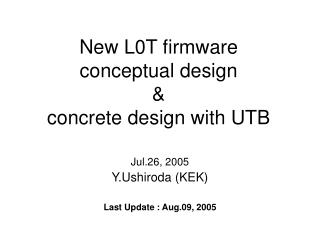
New L0T firmwareconceptual design&concrete design with UTB Jul.26, 2005 Y.Ushiroda (KEK) Last Update : Aug.09, 2005
Input/Output Input Signals TOF 32 bit (64 or 128 in future) (LVDS) TSF 64 bit (LVDS) (future) GDL L1 (from SEQ) (ECL) Output Signals 1 L0 to Minomo (NIM) (future) 1 Hold to Minomo (NIM) (future) 1 Hold to Minomo (NIM) + 10 Holds to Dock (LVDS) Output Signals to be monitored Busy(1) L0(1), L1(1), Hold(1), Nclst(3) 64 TSF 32 TSF&TOF
B A D C F E H G J I L K N M I/O can be chosen per 16 channels. In practice, will be chosen per connector (32 channels) as follows: Pins={0,0} : input, {1,1} : output
I/O can be chosen per 16 channels. In practice, will be chosen per connector (32 channels) as follows: B A D C E F H G J I L K N M Pins={0,0} : input, {1,1} : output Modified on Dec.07
16 or 24ns 12ns 14ns In Out Latency / System clock External 64MHz clock in NIM through a LEMO in the front panel (GCK1/P44) Alternatively, internal 42.3333MHz clock on the board (GCK2/P46) The entire logic is hoped to fit in 50ns. The minimal latency (just to go through) from flat cable input to flat cable output is typically 22 ns. LEMO to LEMO latency is about 29ns. Flat cable input (iog<1>) to LEMO (trgout) output is about 26ns Just 1 clock (16ns) available. or 3 (24ns) with using internally doubled 128MHz clock Total (50+D)ns, where D>Tps = 5.12 ns with XC3S4000-4
Reset • There are three sources of reset signals: • Power on reset (ponrst) • Push button reset (swrst) • Reset via VME. (vmerst) • All of them are ORed to one single rst_ signal (negative-true logic)
VME bus Address Module base address can be specified with S2. a31 to a24 must match with S2 settings. Lower bits (a23..a1) can be used in CPLD and in FPGA CPLD uses subspace of a23 == 0 FPGA uses subspace of a23 == 1 AM Only the following AMs are supported: 6'h09 U32 data 6'h0a U32 program 6'h0d S32 data 6'h0e S32 program Data Only D7..D0 go into CPLD All 32 data lines go into FPGA • To be controlled: • clock source • input delay/width (0~T, 2~W) • number of TSF for 1 TOF (max M) • multiplicity (>=2 default, max N) • L0/Hold width ()
J0 bus Not to be used
1 32 1 11 1 64 Conceptual Design Delay&Width Adj. Track (or Cluster) Counting Track Finding TOF 32 Discrimination L0 32 3 32 TSF 64 <16ns <8ns 10.665ns 8.389ns (as of Aug.09) <8ns (optional) Anticipation of L1 L0 Hold L1
11 1 1 32 1 64 (optional) Anticipation of L1 L0 Hold L1 Conceptual Design 2 Delay&Width Adj. Track (or Cluster) Counting Track Finding TOF 32 Discrimination L0 32 3 32 TSF 64 <16ns <16ns <8ns Opening Angle (<8ns) 64 1 64 64 <8ns
FPGA_IO Up to FPGA_IO 35
LED CPLD FPGA