Download
1 / 99
990 likes | 1.14k Vues
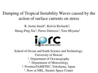
DIAGNOSTICS FOR OBSERVATION and DAMPING of E-P INSTABILITY. Vadim Dudnikov FERMILAB, December 2005. Motivation. For observation and damping of e-p and ion-beam instability it is important to use adequate diagnostics

E N D
DIAGNOSTICS FOR OBSERVATION and DAMPING of E-P INSTABILITY Vadim Dudnikov FERMILAB, December 2005
Motivation • For observation and damping of e-p and ion-beam instability it is important to use adequate diagnostics • For verification of computer codes for instability simulation it is important to have a reliable experimental date in simple conditions. • Experiments in small scale low energy rings can be used for quantitative verification of simulation codes and for development of methods for instability damping . • Informative diagnostics is important for collection of necessary information.
Outline • e-p instability: historical remarks and references • Small scale Proton Storage Rings • Diagnostics • Observations • Damping of e-p instability • Production of a stable space charge compensated circulating beam with high intensity
Abstract • Diagnostics for observation, identification and damping of instabilities driven by interaction with secondary plasma in storage rings and synchrotrons will be considered. • Clearing electrodes, fast gauges, fast valves, fast extractors, repulsing electrodes, electron and ion collectors with retarding grids, particle spectrometers used for the detection of secondary particle generation and secondary particle identification will be discussed. • Features of electrostatic and magnetic dipole and quadrupole pickups will be presented. • The influence of nonlinear generation of secondary plasma in driving and stabilization of e-p instability will be discussed. • Observations of anomaly in secondary particle generation will be presented. • Conditions for accumulation of proton beam with intensity greater than space charge limit will be discussed.
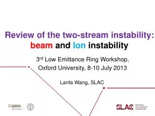
Two-stream instability, historical remarks • Beam instability due to compensating particles were first observed with coasting proton beam and long proton bunches at the Novosibirsk INP(1965), the CERN ISR(1971), and the Los Alamos PSR(1986)… • Recently two-stream instability was observed in almost all storage rings with high beam intensity. • Observation of two-stream instability in different conditions will be reviewed. • Diagnostics and damping of two-stream instability will be discussed.
Two-stream instability • Beam interaction with elements of accelerator and secondary plasma can be the reason for instabilities, causing limited beam performance. • Improving of vacuum chamber design and reducing of impedance by orders of magnitude relative with earlier accelerators increases threshold intensity for impedance instability. • Two-stream effects (beam interaction with a secondary plasma) become a new limitation on the beam intensity and brightness. Electron and Antiproton beams are perturbed by accumulated positive ions. • Proton and positron beams may be affected by electrons or negative ions generated by the beam. These secondary particles can induce very fast and strong instabilities. • These instabilities become more severe in accelerators and storage rings operating with high current and small bunch spacing. .
This instability is a problem for heavy ion inertial fusion, but ion beam with higher current density can be more stable. Instability can be a reason of fast pressure rise include electron stimulated gas desorbtion, ion desorbtion, and beam loss/halo scraping. Beam induced pressure rise had limited beam intensity in CERN ISR and LEAR. Currently, it is a limiting factor in RHIC, AGS Booster, and GSI SIS. It is a relevant issue at SPS, LANL PSR, and B-factories. For projects under construction and planning, such as SNS, LHC, LEIR, GSI upgrade, and heavy ion inertial fusion, it is also of concern.
First project of proton/antiproton collider VAPP, in the Novosibirsk INP (BINP), 1960 • Development of charge-exchange injection (and negative ion sources) for high brightness proton beam production. First observation of e-p instability. • Development of Proton/ Antiproton converter. • Development of electron cooling for high brightness antiproton beam production. • Production of space charge neutralized proton beam with intensity above space charge limit. Inductance Linac, Inertial Fusion, Neutron Generators.
History of Charge Exchange Injection(Graham Rees, ISIS , ICFA Workshop) 1. 1951 Alvarez, LBL (H-) ; 1956 Moon, Birmingham Un. (H+2) 2. 1962-66 Budker, Dimov, Dudnikov, Novosibirsk ; first achievements; discovery of e-p instability.IPM 3. 1968-70 Ron Martin, ANL ; 50 MeV injection at ZGS 4. 1972 Jim Simpson, ANL ; 50-200 MeV, 30 Hz booster 5. 1975-76 Ron Martin et al, ANL ; 6 1012 ppp 6. 1977 Rauchas et al, ANL ; IPNS 50-500 MeV, 30 Hz 7. 1978 Hojvat et al, FNAL ; 0.2-8 GeV, 15 Hz booster 8. 1982 Barton et al, BNL ; 0.2-29 GeV, AGS 9. 1984 First very high intensity rings ; PSR and ISIS 10. 1980,85,88 IHEP, KEK booster, DESY III (HERA) 11. 1985-90 EHF, AHF and KAON design studies. SSC 12. 1992 AGS 1.2 GeV booster injector 13. 1990's ESS, JHF and SNS 4-5 MW sources
History of Surface Plasma Sources Development BDD, G.Budker, G.Dimov, V.Dudnikov Charge-Exchange Injection
INP Novosibirsk, 1965, bunched beam Other INP PSR 1967: coasting beam instability suppressed by increasing beam current; fast accumulation of secondary plasma is essential for stabilization; 1.8x10¹² in 6 m first observation of an e- driven instability? coherent betatron oscillations & beam loss with bunched proton beam; threshold~1-1.5x10¹⁰, circumference 2.5 m, stabilized by feedback (G. Budker, G. Dimov, V. Dudnikov, 1965). F. Zimmermann V. Dudnikov, PAC2001, PAC2005
ISR, coasting proton beam, ~1972 (R. Calder, E. Fischer, O. Grobner, E. Jones) excitation of nonlinear resonances; gradual beam blow up similar to multiple scattering beam induced signal from a pick up showing coupled e-p oscillation; beam current is 12 A and beam energy 26 GeV 2x10-11 Torr, 3.5% neutralization, DQ=0.015 • Damped by extensive system of electrostatic clearing electrodes
PSR instability, 1988 (D. Neuffer et al, R. Macek et al.) beam loss on time scale of 10-100 ms above threshold bunch charge of 1.5x10¹³, circumference 90 m, transverse oscillations at 100 MHz frequency beam current and vertical oscillations; hor. scale is 200 ms/div.
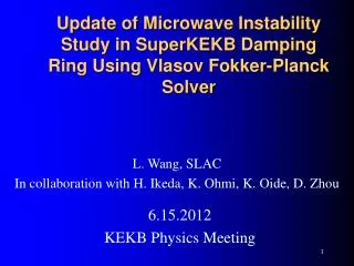
AGS Booster, 1998/99(M.Blaskiewicz) time 5 beam current [A] y power density 500 ms -500 ms 0.2 GHz coasting beam vertical instability growth time ~3 ms ~100 MHz downward shift as instability progresses
KEKB e+ beam blow up, 2000(H. Fukuma, et al.) IP spot size half of solenoids on threshold of fast vertical blow up all solenoids off all solenoids on slow growth below threshold? beam current, mA
Evidence of electron cloud build-up in DAFNE (PAC05, FPAP001,002) Vacuum pressure read-out vs. total current as recorded in four straight section locations for the electron (blue dots) and positron (red dots) rings.
Evidence of electron cloud build-up in DAFNE (PAC05, FPAP001) Vacuum pressure read-out vs. total current as recorded in 2 straight section of the positron ring where a 50 G solenoid field was turned on (red dots) and off (blue dots).
Simulation of electron cloud build-up in DAFNE (PAC05, FPAP001) Electron cloud build-up along two bunch trains for the drift downstream of the arc: a) simple drift, b) drift with residual magnetic field of By≈ .1 T, c) drift with a 50 G solenoid. (Primary electron rate dλe/ds= 0.26)
Why no e-p Instability in the ISIS? Exotic vacuum chamber? Defocusing, scattering of secondary electrons? Collect electrons as black body?
ISIS has much larger a and b, and low particle density. Bounce frequency is low . Only low modes of betatron oscillations are unstable. This lead to removing of electrons without beam loss.
Referenceswww.google.com two-stream transverse instability… http://wwwslap.cern.ch/collective/electron-cloud/.
Historical remark V.Dudnikov.Ph.D.thesis,1966
References for first observation of e-p instability • V.Dudnikov, “The intense proton beam accumulation in storage ring by charge- exchange injection method”, Ph.D.Thesis, Novosibirsk INP,1966. • G. Budker, G. Dimov, V. Dudnikov, “Experiments on production of intense proton beam by charge exchange injection method” in Proceedings of International Symposium on Electron and Positron Storage Ring, France,Sakley,1966, rep. VIII, 6.1 (1966). • G. Budker, G. Dimov, V. Dudnikov, “Experimental investigation of the intense proton beam accumulation in storage ring by charge- exchange injection method”, Soviet Atomic Energy, 22, 384 (1967). • G.Budker, G.Dimov, V. Dudnikov, V. Shamovsky, “Experiments on electron compensation of proton beam in ring accelerator”, Proc.VI Intern. Conf. On High energy accelerators, 1967, MIT & HU,A-104, CEAL-2000, (1967). • G.I.Dimov, V.G.Dudnikov,V.G.Shamovsky, ” Transverse instability of a proton beam due to coherent interaction with a plasma in a circular accelerator” Soviet Conference on Charge- particle accelerators”,Moscow,1968, translation from Russian, 1 1973 108565 8. • G. Dimov, V. Dudnikov, V. Shamovsky, “Investigation of the secondary charged particles influence on the proton beam dynamic in betatron mode ”, Soviet Atomic Energy, 29,353 (1969). • Yu.Belchenko, G.Budker, G.Dimov, V.Dudnikov, et al. X PAC,1977. • O.Grobner, X PAC,1977. • E. Colton, D. Nuffer, G. Swain, R.Macek, et al., Particle Accelerators, 23,133 (1988).
Models of two-streaminstability • The beam- induces electron cloud buildup and development of two-stream e-p instability is one of major concern for all projects with high beam intensity and brightness [1,2]. • In the discussing models of e-p instability, transverse beam oscillations is excited by relative coherent oscillation of beam particles (protons, ions, electrons) and compensating particles (electrons,ions) [3,4,5]. • For instability a bounce frequency of electron’s oscillation in potential of proton’s beam should be close to any mode of betatron frequency of beam in the laboratory frame. 1. http://wwwslap.cern.ch/collective/electron-cloud/. 2. http://conference.kek.jp/two-stream/. 3. G.I.Budker, Sov.Atomic Energy, 5,9,(1956). • B.V. Chirikov, Sov.Atomic.Energy,19(3),239,(1965). • Koshkarev, Zenkevich, Particle Accelerators, (1971). 6. M.Giovannozzi, E.Metral, G.Metral, G.Rumolo,and F. Zimmerman , Phys.Rev. ST-Accel. Beams,6,010101,(2003).
Memo from: Bruno Zotterwww.aps.anl.gov/conferences/icfa/twoo-stream/ • Subject: Summary of my own conclusions of the workshop • 1) Go on with your plans to coat the most sensitive locations in the PSR (Al stripper chamber, sections with ceramics and with high losses) with Ti nitride - make sure that the deposition technique avoids rapid flaking off; • 2) If this is not sufficiently successful, install a transverse feedback system based on the wide-band split cylinder pickups - Dudnikov showed an example where a simple feedback seemed to work fine on e-p. If the oscillations are kept sufficiently small by it, there may be no need for high power;
Development of Charge Exchange Injection and Production of Circulating Beam with Intensity Greater than Space Charge Limit V.Dudnikov. “Production of an intense proton beam in storage ring by a charge- exchange injection method”, Novosibirsk, Ph.D.Thesis,INP, 1966. Development of a Charge- Exchange Injection; Accumulation of proton beam up to space charge limit; Observation and damping of synchrotron oscillation; Observation and damping of the coherent transverse instability of the bunched beam. Observation of the e-p instability of coasting beam in storage ring. G. Budker, G. Dimov, V. Dudnikov, “Experiments on production of intense proton beam by charge exchange injection method” in Proceedings of International Symposium on Electron and Positron Storage Ring, France,Sakley,1966, rep. VIII, 6.1 (1966). G. Budker, G. Dimov, V. Dudnikov, “Experimental investigation of the intense proton beam accumulation in storage ring by charge- exchange injection method”, Soviet Atomic Energy, 22, 384 (1967). G.Dimov, V.Dudnikov, “Determination of circulating proton current and current density distribution (residual gas ionization profile monotor)”, Instrum. Experimental Techniques, 5, 15 (1967). Dimov. “Charge- exchange injection of protons into accelerators and storage rings”, Novosibirsk, INP, 1968. Development of a Charge- Exchange Injection; Accumulation of a proton beam up to the space charge limit; Observation and damping of synchrotron oscillations; Observation and damping of the coherent transverse instability of the bunched beam;. Shamovsky. “Investigation of the Interaction of the circulating proton beam with a residual gas”, Novosibirsk, INP, 1972. Observation of transverse e-p coherent instability of the coasting beam in the storage ring, Observation of a transverse Herward’s instability, Damping of instabilities, Accumulation of a proton beam with a space charge limit. G. Dimov, V. Dudnikov, V. Shamovsky, “Transverse instability of the proton beam induced by coherent interaction with plasma in cyclic accelerators”, Trudy Vsesousnogo soveschaniya po uskoritelyam, Moskva, 1968, v. 2, 258 (1969). G. Dimov, V. Dudnikov, V. Shamovsky, “Investigation of the secondary charged particles influence on the proton beam dynamic in betatron mode ”, Soviet Atomic Energy, 29,353 (1969). G.Budker, G.Dimov, V. Dudnikov, V. Shamovsky, “Experiments on electron compensation of proton beam in ring accelerator”, Proc.VI Intern. Conf. On High energy accelerators, 1967, MIT & HU,A-104, CEAL-2000, (1967). Chupriyanov. “Production of intense compensated proton beam in an accelerating ring”, Novosibirsk, INP, 1982. Observation and damping transverse coherent e-p instability of coasting proton beam and production of the proton beam with an intensity up to 9.2 time above a space charge limit. G.Dimov, V.Chupriyanov, “Compensated proton beam production in an accelerating ring at a current above the space charge limit”, Particle accelerators, 14, 155- 184 (1984).Yu.Belchenko, G.Budker, G.Dimov, V.Dudnikov, et al.X PAC,1977.
General view of INP PSR with charge exchange injection 1965 • Magnet • Vacuum chamber • Beam line • 5. First stripping target • 6. Second stripping target
INP PSR for bunched beam accumulation by charge exchange injection 1- fist stripper; 2- main stripper Pulsed supersonic jet; 3- gas pumping; 4- pickup integral; 5- accelerating drift tube; 6- gas luminescent profile Monitor; 7- Residual gas current monitor; 8- residual gas IPM; 9- BPM; 10- transformer Current monitor; 11- FC; 12- deflector for Suppression transverse instability by negative Feedback. Small Radius- High beam density. Revolution 5.3 MHz. 1MeV, 0.5 mA, 1 ms.
PSR for Circulating p-Beam Production 1-striping gas target; 2-gas pulser; 3-FC; 4-Q screen; 5,6-moving targets; 7-ion collectors; 8-current monitor; 9-BPM; 10-Q pick ups; 11-magnetic BPM; 12-beam loss monitor; 13-detector of secondary particles density; 14-inductor core; 15-gas pulsers; 16-gas leaks. Proton Energy -1 MeV; injection-up to 8 mA; bending radius-42 cm; magnetic field-3.5 kG;index-n=0.2-0.7; St. sections-106 cm;aperture-4x6 cm; revolution-1.86 MHz; circulating current up to 300mA is up to 9 time greater than a space charge limit.
Vacuum control • Stripping target- high dense supersonic hydrogen jet (density up to e19 mol/cm3, target e17 mol/cm2 , ~1ms) • Vacuum e-5 Torr • Fast, open ion gauges • Fast compact gas valves, opening of 0.1 ms.
1 -current feedthrough; 2- housing; 3-clamping screw; 4-coil; 5- magnet core; 6-shield; 7-screw; 8-copper insert; 9-yoke; 10-rubber washer- returning springs; 11-ferromagnetic plate- armature; 12-viton stop; 13-viton seal; 14-sealing ring; 15-aperture; 16-base; 17-nut. Fast, compact gas valve, 0.1ms, 0.8 kHz,tested for >109Pulses, operate 12 Years in BNL H- magnetron SPS
Proton beam accumulation for different injection current (0.1-0.5 mA) Injected beam Circulating beam, Low injection current Start saturation Strong saturation
Residual gas ionization beam current & profile monitors (ICM,IPM),1965
Residual gas luminescent beam profile monitor, INP,1965 1- magnetic pole; 2- proton beam; 3- moving collimator 4- light guide; 5-photomultiplier; 6-vacuum chamber
Fermilab IPM • Mark-II details Secondary Screen Grid J.Zagel RF Shield Over MCP
Internal Structure, FNAL IPM • Main Injector • Electrostatic Unit J.Zagel
Signal and Timing • Typical Amplified Strip Signal • Relative to Beam Sync Clock (Captured in Recycler) J.Zagel
Interesting Observations • Plate Discoloration from long term exposure to beam • Diamondlike film deposition
CERN Luminescence Profile Monitor • It works with N2 injection 1 light channel is going to a PM for gas-luminescence studies (decay time etc.) • 2 channels are used for profile measurements: • The H channel is in air: it showed high background with LHC beam, due to beam losses • The V channel is in vacuum • The MCP has a pre-programmed variable gain over cycle (it showed some problems to log on timing events)