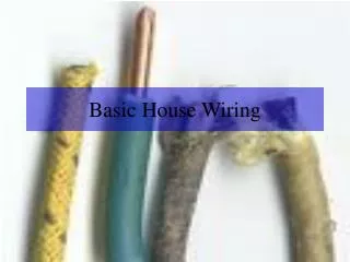
Basic Thermostat Wiring
Basic Thermostat Wiring. North Seattle Community College HVAC Program Instructor – Mark T. Weber, M.Ed.

Basic Thermostat Wiring
E N D
Presentation Transcript
Basic Thermostat Wiring North Seattle Community College HVAC Program Instructor – Mark T. Weber, M.Ed.
A thermostat is a component of a control system which senses the temperature of a structure or part of a structure so that the temperature is maintained near a desired setpoint. The thermostat does this by switching heating or cooling devices on or off, or regulating the flow of a heat transfer fluid as needed, to maintain the correct temperature. • A thermostat may be a control unit for a heating or cooling system or a component part of a heater or air conditioner. Thermostats can be constructed in many ways and may use a variety of sensors to measure the temperature. The output of the sensor then controls the heating or cooling apparatus. A Thermostat may switch on and off at temperatures either side of the setpoint the extent of the difference is known as hysteresis and prevents too frequent switching of the controlled equipment. • The first electric room thermostat was invented in 1883 by Warren S. Johnson (Johnson Controls). Early technologies included mercury thermometers with electrodes inserted directly through the glass, so that when a certain (fixed) temperature was reached the contacts would be closed by the mercury. These were accurate to within a degree of temperature.
The majority of modern heating/cooling/heat pump thermostats operate on low voltage (typically 24 volts AC) control circuits. The source of the 24 volt AC power is a control transformer installed as part of the heating/cooling equipment. • The advantage of the low voltage control system is the ability to operate multiple electromechanical switching devices such as relays, contactors, and sequencers using inherently safe voltage and current levels. Built into the thermostat is a provision for enhanced temperature control using anticipation. This opens the heating contacts slightly early to prevent the space temperature from greatly overshooting the thermostat setting
Terminal Function R 24V Power W First stage or primary heat W2 Auxiliary or second stage heat Y1 First stage or primary cooling Y2 Second stage cooling G Blower fan relay O Reversing valve S1 Outdoor temp sensor S2 Outdoor temp sensor
Cooling mode Heating mode 77.5 call for cooling - on 77 degree set point Heating and cooling regulation Depending on what is being controlled, a forced-air air conditioning thermostat generally has an external switch for heat/off/cool, and another on/auto to turn the blower fan on constantly or only when heating and cooling are running Modern thermostats have a relatively tight set range for operation. In the heating mode with the set point at 70 degrees, the thermostat will not call for heat until the ambient temperature has reached 69.5 degrees. The display will still read 70 degrees. When the ambient temperature reaches 70.5 degrees, the thermostat will end the call for heat. In the cooling mode with the set point 77 degrees, the thermostat will call for cooling when the ambient temperature reaches 77.5 degrees. When the ambient temperature reaches 76.5 degrees, the thermostat will end the call for cooling. 76.5 call for cooling - off 70.5 call for heat - off 70 degree set point 69.5 call for heat - on
Newer digital thermostats have no moving parts to measure temperature and instead rely on thermistors or other semiconductor devices. A clock and time-of-day and day-of-week settings for the temperature are used for comfort and energy conservation. Some advanced models have touch screens, or the ability to work with home automation or building automation systems. More expensive models have a built-in Adaptive Intelligent Recovery controller (learned logic), so that the thermostat knows ahead how the system will react to its commands. For instance, setting it up that temperature in the morning at 7 a.m. should be 70F, the AIR makes sure that at that time the temperature will be 70F, where a conventional thermostat would just start working at that time. The AIR controller decides at what time the system should be activated in order to reach the desired temperature at the desired time based on several factors such as outdoor temperature and the average length of time it took to raise the temperature the past 5 times.
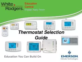
The following slides will give you the basic wiring for a Honeywell Elite Thermostat. This is probably the most common thermostat on the market but be sure to follow the set-up instructions for any thermostat you install.
Single stage furnace The thermostat connections for a single-stage gas furnace are fairly straight forward. The red wire is connected to “R” and this supplies 24VAC to energize the various functions. The blue wire is connected to “C” and this is the return for the clock, calendar and other programming functions of the thermostat. It DOES NOT supply voltage to activate “O”, “G”, “W”, etc. The green wire is connected to “G” and activates the blower FAN RELAY. There is a bridge between “W1” and “W2”. This stays in place and the white wire is connected to “W” which will activate the start-up sequence for the furnace. On a call for heat, “W” and “G” are activated.
Single stage furnace w/ A/C A single stage-gas furnace with A/C has one more wire. A yellow wire is connect to “Y” and on a call for cooling activates the compressor contractor. “G”(Blower fan relay) is also activated. OD Unit
Two-stage Furnace W/ A/C On a two-stage gas furnace, the bridge between “W1” and “W2” is removed. The white wire is connected to “W1” and to “W1” in the furnace. Another wire, in this case brown, is connected to “W2” in the thermostat and “W2” in the furnace. On a call for heat, the thermostat will activate “W1”. Some thermostats allow the technician to program the length of time, the outside temperature set-point, or if the temperature increase is greater than a determined amount before “W2” is activated and some do not. If the upper set-point is not reached by a certain length of time or if the other factors, such as outdoor temp, amount of heat, then “W2” is activated. OD Unit
The thermostat set-up for a heat pump is set up differently than for a gas or oil furnace. When a heat pump is in the heating mode, the reversing valve (O) is de-energized. When the thermostat is switched to cooling, the reversing valve (O) is energized. On a call for heat, “Y” (Compressor contactor) and “G” (Blower fan relay) are energized. On a call for cooling, “Y” (Compressor contactor), “G” (Blower fan relay), and (O) (reversing valve) are energized. Auxiliary and emergency heat are called for when the heat pump is not able to satisfy the call for heat. This can be programmed into the thermostat by the installer and overridden by the homeowner. When auxiliary heat is a gas furnace (dual fuel), when the need for auxiliary is reached, thermostat will “lock-out” the compressor and only the gas furnace will operate. Except when in defrost mode, both units will not operate at the same time. OD Unit
When installing a thermostat only, be sure to check the wire color connections at the furnace or heat pump. DO NOT assume they were connected using the same wire colors. • Once the thermostat is installed it has to be programmed. The items usually programmed by the installer are: • Date, day of week and clock • Temp display scale (Celsius or Fahrenheit) • Whether the unit is gas, oil, heat pump, heat with electric auxiliary heat, dual fuel. • Remote outdoor temperature sensor (present or not) • Fan controls • Cycles per hour (min and max) • Heat pump compressor lock out (temperature) • Auxiliary heat lock out (temperature) • Filter change reminder • UV light change reminder • Adaptive Intelligent Recovery (yes or no) • Once the thermostat is programmed, the installer goes through a series of systems check with the thermostat is ensure the system is operating properly.
I’ve done some crazy stuff in my time but this is absolutely nuts!!!!!