
Border Gateway Protocol (BGP) and Routing Protocols
E N D
Presentation Transcript
Intra-AS v.s. Inter-AS Intra-AS Inter-AS
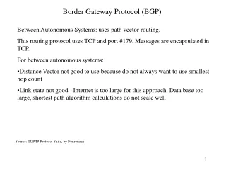
Path vector routing • Path vector v.s. Distance vector • Speaker node • creates a routing table • advertises routing table to speaker nodes in the neighboring ASs.
BGP Messages • BGP messages exchanged using TCP on port 179.
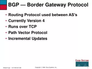
BGP Function • BGP provides each AS a means to: • Obtain subnet reachability information from neighboring ASs. • Propagate reachability information to all AS-internal routers. • Determine“good” routes to subnets based on reachability information and policy. • allows subnet to advertise its existence to rest of Internet: “I am here”
2c 2b 3c 1b 1d 1c Distributing reachability info • using eBGP session between 3a and 1c, AS3 sends prefix reachability info to AS1. • 1c can then use iBGP do distribute new prefix info to all routers in AS1 • 1b can then re-advertise new reachability info to AS2 over 1b-to-2a eBGP session • when router learns of new prefix, it creates entry for prefix in its forwarding table. eBGP session iBGP session 3a 3b 2a AS3 AS2 1a AS1
Why different Intra- and Inter-AS routing ? Policy: • Inter-AS: admin wants control over how its traffic routed, who routes through its net. • Intra-AS: single admin, so no policy decisions needed Scale: • hierarchical routing saves table size, reduced update traffic Performance: • Intra-AS: can focus on performance • Inter-AS: policy may dominate over performance
CHAPTER 24 • Congestion Control and Quality of Service
Congestion Control • When one part of the subnet (e.g. one or more routers in an area) becomes overloaded, congestion results. • Because routers are receiving packets faster than they can forward them, one of two things must happen: • The subnet must prevent additional packets from entering the congested region until those already present can be processed. • The congested routers can discard queued packets to make room for those that are arriving.
Factors that Cause Congestion • Packet arrival rate exceeds the outgoing link capacity. • Insufficient memory to store arriving packets • Bursty traffic • Slow processor
Congestion control and quality of service are two issues so closely bound together that • improving one means improving the other and ignoring one usually means ignoring the other.
Load Shedding • When buffers become full, routers simply discard packets. • Which packet is chosen to be the victim depends on the application and on the error strategy used in the data link layer. • For a file transfer, for, e.g. cannot discard older packets since this will cause a gap in the received data. • For real-time voice or video it is probably better to throw away old data and keep new packets. • Get the application to mark packets with discard priority.
So the policy for file transfer is called WINE(old is better than new ). • And the policy for multimedia is called MILK(new is better than old )
24-1 DATA TRAFFIC The main focus of congestion control and quality of service is data traffic. In congestion control we try to avoid traffic congestion. In quality of service, we try to create an appropriate environment for the traffic. So, before talking about congestion control and quality of service, we discuss the data traffic itself.
An important issues in Packet Switched Network i.e congestion
Traffic Descriptor Traffic descriptors are qualitative values that represent a data flow.
Traffic Profiles For our purposes, a data flow can have one of the following traffic profiles: constant bit rate, variable bit rate, or bursty In the bursty data category, the data rate changes suddenly in a very short time. It may jump from zero, for example, to 1 Mbps in a few microseconds and vice versa
24-2 CONGESTION Congestion in a network may occur if the load on the network—the number of packets sent to the network—is greater than the capacity of the network—the number of packets a network can handle. Congestion control refers to the mechanisms and techniques to control the congestion and keep the load below the capacity. Topics discussed in this section: Network Performance
Figure 24.3 Queues in a router it undergoes three steps before departing,
There are mainly two issues which cause congestion. • The first issues is that if the rate of the packet arrival is higher than the packet processing rate, input queue becoming longer and longer. • If the packet departure rate is less than the packet processing rate the output queue become longer and longer
24-3 CONGESTION CONTROL Congestion control refers to techniques and mechanisms that can either prevent congestion, before it happens, or remove congestion, after it has happened. In general, we can divide congestion control mechanisms into two broad categories: open-loop congestion control (prevention) and closed-loop congestion control (removal). Topics discussed in this section: Open-Loop Congestion ControlClosed-Loop Congestion Control
The retransmission policy and the retransmission timers must be designed to optimize efficiency and at the same time prevent congestion
If the receiver does not acknowledge every packet it receives, it may slow down the sender and help prevent congestion The Selective Repeat window is better than the Go-Back-N window for congestion control.
A good discarding policy by the routers may prevent congestion and at the same time may not harm the integrity of the transmission A router can deny establishing a virtual circuit connection if there is congestion in the network or if there is a possibility of future congestion.
Selective repeat window is better Should send cumulative ack Higher priority packets should not be discard
Implicit- by symptom source will aware about congestion in network Explicit signal- send control data Backward signaling- warning source (opposite direction to congestion) Forward signaling
Implicit- by symptom source will aware about congestion in network Explicit signal- send control data Backward signaling- warning source (opposite direction to congestion) Forward signaling
24-6 TECHNIQUES TO IMPROVE QoS In Section 24.5 we tried to define QoS in terms of its characteristics. In this section, we discuss some techniques that can be used to improve the quality of service. We briefly discuss four common methods: scheduling, traffic shaping, admission control, and resource reservation. Topics discussed in this section: SchedulingTraffic ShapingResource Reservation Admission Control
Different applications need different bandwidths. In video conferencing we need to send millions of bits per second to refresh a color screen while the total number of bits in an e-mail may not reach even a million. Again applications can tolerate delay in different degrees Source-to-destination delay is another flow characteristic For example, it is more important that electronic mail, file transfer, and Internet access have reliable transmissions than telephony or audio conferencing. In this case, telephony, audio conferencing, video conferencing, and remote log-in need minimum delay, while delay in file transfer or e-mail is less important. Reliability is a characteristic that a flow needs. Lack of reliability means losing a packet or acknowledgment, which entails retransmission. Jitter is the variation in delay for packets belonging to the same flow. For example, if four packets depart at times 0, 1, 2, 3 and arrive at 20, 21, 22, 23, all have the same delay, 20 units of time. On the other hand, if the above four packets arrive at 21, 23, 21, and 28, they will have different delays: 21,22, 19, and 24. Jitter is defined as the variation in the packet delay. High jitter means the difference between delays is large; low jitter means the variation is small.
Figure 24.16 FIFO queue In first-in, first-out (FIFO) queuing, packets wait in a buffer (queue) until the node (router or switch) is ready to process them. If the average arrival rate is higher than the average processing rate, the queue will fill up and new packets will be discarded. A FIFO queue is familiar to those who have had to wait for a bus at a bus stop. Figure shows a conceptual view of a FIFO queue.