

Abstract
E N D
Presentation Transcript
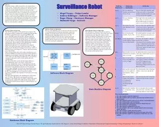
Surveillance Robot Abstract This project attempts to address the need for a self-contained home security system. Currently, home security systems require many costly components and a complicated installation process. Two basic types of systems are currently available. The first is a wired system. One drawback is that installation of a wired system can take a lot of time and money. Another drawback is that it is a permanent part of the home. If the owner moves, the security system must stay. The second type of system is a wireless one. These components for this are also costly. Wireless systems are more mobile, but they require batteries which must be changed every so often. The purpose of the proposed system will be to eliminate the drawbacks of both wired and wireless systems. The proposed system will consist of a single unit, which will monitor the home for various hazardous conditions. Hardware Theory of Operation Four 24V DC gear motors will be utilized for locomotion. The motor driver will be a commercially assembled part that provides the ability to control the motor's speed using PWM. It will receive the PWM signal from the MCU and then output the driver current to the motor. Each driver will be configured to drive two motors out of the four. In this manner, we will be able to turn the robot on a time and navigate through the environment with precision. This is important when implementing a mapping algorithm that requires accurate movement. Fuses are implemented to provide over current protection to keep the motors safe. Each of the motors will be fitted with a 71:1 gear reduction ratio. The theoretical rating for these motors will be 91 RPM at no load, a rated torque of 3.1 kgf-cm, and a rated current of less than 250mA. Safety concerns on the robot will be addressed with the use of a mechanical ESTOP. A mechanical push button will be utilized in tripping the circuit breakers connected to the output of the power sources. Thus, once the E-Stop is pushed, power to all electronic components and motors will be cut off, and the robot will suspend motion. The sensors that will be used on the Surveillance Robot is a Carbon Monoxide sensor, a UV sensor, a audio sensor, a gyroscope, and proximity sensors. Using information from the gyroscope and the proximity sensors, the robot's position can be determined. Using information from the CO, UV, and audio sensors, alarm conditions can be detected. Data from the sensors is amplified to the MCU's operating voltage and is processed in the MCU for alarming the user via transceivers and for locomotion. The MCU will communicate with transceivers using SPI protocol. The robot will be powered by the combination of a 24V battery and a 5V battery. The batteries are chargeable and will be charged by a 24V charger and a 5V charger. A power plug can be plugged into the standard 125V, 60Hz and the voltage will be conditioned by both the battery chargers so that the batteries can be charged. Software Theory of Operation The basic idea behind this layer of software is that the sensor data is read from the Sensor I/O module and used in a finite state machine. It will send control signals to the Locomotive and Warning modules depending on what state it is in. The locomotive module will then take these control signals and determine exactly how far to move the robot. The warning module will also warn the user when a threat is in the proximity of the robot and log this information. State Machine Theory of Operation The following state diagram describes the different states that the system can be in. The system starts off an in initialization state where the counters and the registers are initialized. It then moves to a processing state which reads the values from the sensors and determines what to do next. If there is a hazard, the state is moved to warning and the warning module is notified. If there is not a hazard detected and the counter for number of movements is not at the max value, the state is moved to the Move state and the Locomotive module is notified of which direction to move to. If the counter value is at its max value, the state is moved to Hibernate where the system will rest for some prescribed amount of time. • Megel Troupe – Project Leader • Andrew Biddinger – Software Manager • Roger Zhang – Hardware Manager • Nathaniel Fargo - Archivist Hardware Block Diagram Software Block Diagram • 2012-2013 Senior Design Capstone Project • Dr. Igor Tsukerman, Faculty Advisor • Mr. Gregory A. Lewis, Senior Design Coordinator • Department of Electrical and Computer Engineering • College of Engineering • University of Akron • State Machine Diagram


