Download
1 / 65
650 likes | 845 Vues
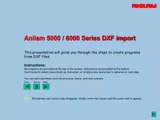
Anilam 5000 / 6000 Series DXF import. This presentation will guide you through the steps to create programs from DXF files. Instructions: Descriptions are provided at the top of the screen, instructions are provided at the bottom.

E N D
Anilam 5000 / 6000 Series DXF import This presentation will guide you through the steps to create programs from DXF files. Instructions: Descriptions are provided at the top of the screen, instructions are provided at the bottom. Use mouse to select menu items as instructed, or simply press space bar to advance to next step. You can also use these icons for previous, home, and next screens. Prev Home Next Note: Sometimes your cursor may disappear, simply move the mouse and the cursor will re-appear.
This is the Manual screen when you first enter the CNC software Select the Program ‘softkey’ from the menu by clicking with mouse
This page shows the programs located in the C:\User directory of the hard drive In the CNC we use a shift key to see more menu options – press space bar or click next now
Display shows additional menu selections (Shift) Click Display ‘softkey’ to change display type
Display now shows file size, date, and time information Using Shift / Display again will show different display options – press space bar or click next
This screen shows all files located on the hard drive Select the DXF file to use, ROBIN2.DXF, in this example – use mouse or next to select
Required DXF file is highlighted Click Utility from the menu
Options from the Utility menu are displayed Click DXF Converter
The DXF drawing file is now displayed. The drawing contains many layers, only some are required, these must be selected To see only the detail we require, click the Layers menu
Display of available options for drawing layers We need to toggle various layers to off so only the required part shape is displayed Click the Toggle Layers menu
All layers are displayed and can be toggled On, or Off. Click 1. 0 ………. On to toggle this layer to Off
Layer 1 is now set to off and will no longer be displayed. We repeat this process to set all non essential layers off. In this example, layer 11 is required. Press space bar to step through all layers, or, use jump to all off button Jump to all off
We repeat this process to set all non essential layers off. In this example, layer 11 is required. Press space bar to step through all layers, or, use jump to all off button Jump to all off
Layer 2 is now set to off and will no longer be displayed. We repeat this process to set all non essential layers off. In this example, layer 11 is required. Press space bar to step through all layers, or, use jump to all off button Jump to all off
Press space bar to step through all layers, or, use jump to all off button Jump to all off
Layer 3 is now set to off and will no longer be displayed. Press space bar to step through all layers, or, use jump to all off button Jump to all off
Press space bar to step through all layers, or, use jump to all off button Jump to all off
Layer 4 is now set to off and will no longer be displayed. Press space bar to step through all layers, or, use jump to all off button Jump to all off
Press space bar to step through all layers, or, use jump to all off button Jump to all off
You get the idea now … Press space bar to step through all layers, or, use jump to all off button Jump to all off
Press space bar to step through all layers, or, use jump to all off button Jump to all off
Press space bar to step through all layers, or, use jump to all off button Jump to all off
Press space bar to step through all layers, or, use jump to all off button Jump to all off
Press space bar to step through all layers, or, use jump to all off button Jump to all off
Press space bar to step through all layers, or, use jump to all off button Jump to all off
Press space bar to step through all layers, or, use jump to all off button Jump to all off
Press space bar to step through all layers, or, use jump to all off button Jump to all off
Press space bar to step through all layers, or, use jump to all off button Jump to all off
Press space bar to step through all layers, or, use jump to all off button Jump to all off
Press space bar to step through all layers, or, use jump to all off button Jump to all off
Layer 11, CONT is the profile of the part and is therefore required - On. Press space bar to step through all layers, or, use jump to all off button Jump to all off
Press space bar to step through all layers, or, use jump to all off button Jump to all off
Press space bar to step through all layers, or, use jump to all off button Jump to all off
Press space bar to step through all layers, or, use jump to all off button Jump to all off
Press space bar to step through all layers, or, use jump to all off button Jump to all off
Press space bar to step through all layers, or, use jump to all off button Jump to all off
Press space bar to step through all layers, or, use jump to all off button Jump to all off
Press space bar to step through all layers, or, use jump to all off button Jump to all off
Press space bar to step through all layers, or, use jump to all off button Jump to all off
Press space bar to step through all layers, or, use jump to all off button Jump to all off
Only layer 11 is set to On. Selection of layers to display is now complete Click Layers again to cancel selection menu
Part profile is now displayed – layer 11 of DXF file Click Display to enlarge the part
Display options are shown – we would like to “fit” the image to our screen Click Fit to automatically display maximum zoom
Here’s a larger image of the part to work on. Now we need to pick geometry elements. Click Select to allow picking of geometry
With Select active, we would now proceed to pick the geometry required via mouse. In this demo, the entire shape is pre-selected. Click next or use space bar for next screen
Selected geometry is highlighted in green. The direction that elements are selected will set direction of cut – climb or conventional milling. Click next or use space bar for next screen
More geometry can simply be selected by clicking. If shapes are not connected, the CNC will ask if you want to connect, in this case N for no as we are selecting a new shape Click next or use space bar for next screen
The CNC will ask if we want to create a new shape. We would answer Y for yes as we are picking a new shape in this example Click next or use space bar for next screen
New selected geometry is highlighted in green, and labeled as shape 2 Click next or use space bar for next screen
Now we’ve selected the geometry or “shapes” required, program options can be set. Click Setup to see program options