Sound recording and playback
340 likes | 577 Vues
Sound recording and playback. Angelo Farina. Physical nature of sound. Origin of Sound:. T hermofluidodynamic phenomen on: Particle velocity and variable density of medium (air). Human body can detect sound (p and v) with: ears, but also skin, chest, stomach.

Sound recording and playback
E N D
Presentation Transcript
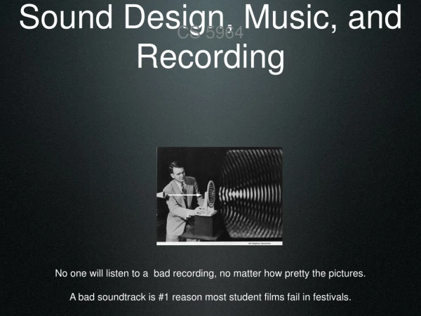
Sound recording and playback • Angelo Farina Sound recording and playback
Physical nature of sound Origin of Sound: Thermofluidodynamic phenomenon: Particle velocity and variable density of medium (air) Human body can detect sound (p and v) with: ears, but also skin, chest, stomach The trasducers should detect the same quantities Sound recording and playback
Transducers: microphones From acoustic pressure and particle velocity to physical (electrical) quantities Output signal: voltage (Volts), current (Amperes) or charge (Coulombs) Pressure microphones (related with acoustic pressure) Velocity microphones (related with particle velocity) Hybrid microphones (a proper combination of both quantities) From omnidirectional (100 p and 0 v) to figure of eight (0 p and 100 v) Sound recording and playback
Microphone directivity patterns Omnidirectional (100,0)Subcardioid(75,25)Cardioid(50,50) Hypercardioid(25,75)Figure-of-Eight(0, 100) Sound recording and playback
Microphones Variable pattern microphone: Neumann U89i variable-pattern microphone Sound recording and playback
Cables The weak microphone signal (few mV/Pa) has to be amplified and transmitted by means of cables Signal contamination can occur inside the cable, if not properly shielded (balanced) with two opposite-polarity signals Balanced audio cables with XLR connectors (3 pins) Sound recording and playback
Preamplifiers • They should simply amplify the signals, but often they also process the signals: • linearly (band pass frequencies), for phantom power supply to mics • non-linearly (compression, harmonic distortion) it should be avoided during room acoustics measurements. 2-channels tube microphone preamplifier Sound recording and playback
ADC (Analog to Digital Converter) Conceptually a black box connecting with two wires: • Analog input (sound signal) • Digital output (serial digital interface) Two different types of ADCs: • PCM converters (Pulse Code Modulation – CD, DAT, DVD) 2. Bitstream converters (DSD, Direct Stream Digital, also called single-bit, employed in SACD). Sound recording and playback
ADC (Analog to Digital Converter) 2 PCM Converters A master clock defines with high precision the instants at which the analog signal has to be “sampled” (Shannon theorem) Sound recording and playback
ADC (Analog to Digital Converter) 3 Low-pass filtering must be applied before entering the ADC, otherwise the signal will be aliased Example: pure tone of 35 kHz Sample rate 48 kHz, Nyquist freq. 24 kHz, difference = 11 kHz After digital conversion will be 13 kHz (i.e. 24-11 kHz) Solution: low-pass antialiasing filters, oversampling Sound recording and playback
ADC (Analog to Digital Converter) 4 Also vertical axis (amplitude) is discretized. Typical resolutions: 16 bits; 20 bits; (24 bits) Example: maximum voltage +5V Discretization with 16 bit (32767 steps) means 90 dB Discretization with 20 bit (524272 steps) means 114 dB High-end, 2-channels ADC unit (24 bits, 192 kHz, Firewire interface) Sound recording and playback
ADC (Analog to Digital Converter) 5 Bitstream Converters • The idea arises from oversampling: increasing sample frequency it would be possible to increase amplitude resolution (bits) • Sample rate: 2.88 MHz and 1 bit resolution: dividing to 2 for 6 time is equivalent to CD audio sample rate, but only with 7 bits! • In order to enhance high freq. resolution, a proper noise shaping of high order is required, suitable for static (non transient) signals. • Below 88 Hz the Bitstream converters outperform PCM conv. Sound recording and playback
ADC (Analog to Digital Converter) 6 Bitstream Converters • The Bitstream converters are widely employed with SACD system (Super Audio CD), co-developed by Sony and Philips. • However they are much more expensive that 24 bit 96 kHz PCM a low-cost multichannel USB-2 soundcard, equipped with 2 microphone preamps Sound recording and playback
Digital Signal Processing Waveform editors sampled waveform displayed as amplitude vs time (time domain) Sound recording and playback
Recording/playback methods • Mono followed by amplitude panning (stereo or surround) • Stereo (ORTF on 2 standard loudspeakers at +/- 30°) • Discrete ITU 5.1 (from different 5-mikes layouts) • Full 3D Ambisonics 1st order (decoding the B-format signal) • 2D Ambisonics 3rd order (from Mark Poletti’s circular array microphone) • Wave Field Synthesis (from the circular array of Soundfield microphones) • Hybrid methods (Ambiophonics) • HOA (high order Ambisonics, Eigenmike) • SPS (Spatial PCM Sampling) Sound recording and playback
Traditional “surround” – amplitude panning • Each mono track is positioned artificially, by means of “pairwise” or “advanced” amplitide panning MIX 5 ch. 5 ch. 5 ch. 1 ch. 1 ch. 5 ch. Surround panner Sound recording and playback
Panning laws • Instead of just feeding a single loudspeaker with each mono track, it is advantageous to “pan” each signal ver two or more loudspeakers Peter Craven’s Ambisonics panning at 5th order – all the loudspeakers are always fed “Pairwise Panning” with constant power- each signal is always sent to just 2 loudspeakers Sound recording and playback
Panning laws • An alternative display of teh spanning laws is by charting the polar patterns of a number of “virtual microphones”, each feeding the corresponding loudspeaker “Pairwise Panning” Peter Craven’s panning Sound recording and playback
ORTF Stereo Playback occurs over a pair of loudspeakers, in the standard configuration at angles of +/- 30°, each being fed by the signal of the corresponding microphone 60° 2 Microphones 2 Loudspeakers Sound recording and playback
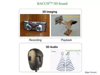
Binaural (Stereo Dipole) xr Cross-talk canceller xl Original 2-channels recording of the signals coming from Nsources Reproduction occurs over 2 loudspeakers angled at +/- 10°, being fed through a “cross-talk cancellation” digital filtering system dNr N … dNl 3 d2r 20° 2 d2l d1r 1 d1l Sound recording and playback
Binaural (Stereo Dipole#2) Sound recording and playback
Binaural (Stereo Dipole#3) frl fll flr frr hrl hll hlr hrr Sound recording and playback
Binaural (Dual Stereo Dipole) Subwoofer Scheme advantages: • 3D sound reproduction • Rotating of the head • The cross-talk filters could equalise also the loudspeakers disadvantages: • Low frequencies • Coloration outside the “sweet spot” Sound recording and playback
Binaural (Dual Stereo Dipole#2) Frontal Rear Quested 2108 monitors Quested F11P monitors Sound recording and playback
“Discrete” microphone arrays • Many different geometrical layouts were proposed – each microphone feeds the corresponding loudspeaker Sound recording and playback
“Discrete” microphone arrays • In a discrete system, each microphone feeds just the corresponding loudspeaker: Microfoni Altoparlanti Sound recording and playback
Schema del sistema microfonico Williams MMA C : Cardioide, 0°L, R : Cardioide, ± 40° LS, RS : Cardioide, ± 120° Schema del sistema microfonico INA-5 C : Cardioide, 0°L, R : Cardioide, ± 90° LS, RS : Cardioide, ± 150° “Discrete” microphone arrays • INA-5 • Williams MMA Sound recording and playback
Schematic of the setup C : Cardioid, 0°L, R : Super Cardioid, ± 90° LS, RS : Cardioid, ± 180° ITU 5.1 surround OCT Sound recording and playback
“Discrete” microphone arrays Why such a limited success? • Little control during recording and during post-processing • Fixed angle of covering, which cannot be adjusted after the recording is done • It makes it difficult to add to the recording the sound track of separately-recorded voices or instruments • Currently available directivity patterns of first-order microphones do not correspond with the ideal, asymmetrical patterns implemented by optimal panning laws. Sound recording and playback