371-1-0291 : An Introduction to Computer Networks
371-1-0291 : An Introduction to Computer Networks. Homepage http://www.cse.bgu.ac.il/Courses/course.asp?ID=63. Handout #2: Foundations and Basic Concepts. Additional Reading Text book: Chaps. 1.2,3.1. Outline. A Detailed FTP Example Layering Packet Switching and Circuit Switching

371-1-0291 : An Introduction to Computer Networks
E N D
Presentation Transcript
371-1-0291: An Introduction to Computer Networks Homepage http://www.cse.bgu.ac.il/Courses/course.asp?ID=63 Handout #2: Foundations and Basic Concepts Additional Reading Text book: Chaps. 1.2,3.1 Computer Networks
Outline • A Detailed FTP Example • Layering • Packet Switching and Circuit Switching • Some terms • Data rate, “Bandwidth” and “throughput” • Propagation delay • Packet, header, address • Bandwidth-delay product, RTT Computer Networks
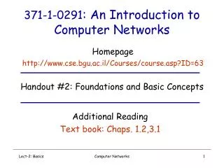
1 20 2 3 4 19 18 17 14 5 15 6 11 8 16 7 12 9 13 10 Example: FTP over the Internet Using TCP/IP and Ethernet App App “A” (BGU) “B” (TECH) OS OS Ethernet Ethernet R5 R1 R2 R3 R4 Computer Networks
In the sending host • Application-Programming Interface (API) • Application requests TCP connection with “B” • Transmission Control Protocol (TCP) • Creates TCP “Connection setup” packet • TCP requests IP packet to be sent to “B” TCP Packet TCP Data TCP Header Type = Connection Setup Empty Computer Networks
TCP Data TCP Header In the sending host (cont.) 3. Internet Protocol (IP) • Creates IP packet with correct addresses. • IP requests packet to be sent to router. TCP Packet Encapsulation Destination Address: IP “B” Source Address: IP “A” Protocol = TCP IP Data IP Header IP Packet Computer Networks
IP Data IP Header In the sending host (cont.) 4. Link (“MAC” or Ethernet) Protocol • Creates MAC frame with Frame Check Sequence (FCS). • Wait for Access to the line. • MAC requests PHY to send each bit of the frame. IP Packet Encapsulation Destination Address: MAC “R1” Source Address: MAC “A” Protocol = IP Ethernet FCS Ethernet Data Ethernet Header Ethernet Packet Computer Networks
IP Data IP Header In Router R1 5. Link (“MAC” or Ethernet) Protocol • Accept MAC frame, check address and Frame Check Sequence (FCS). • Pass data to IP Protocol. IP Packet De-capsulation Destination Address: MAC “R1” Source Address: MAC “A” Protocol = IP Ethernet FCS Ethernet Data Ethernet Header Ethernet Packet Computer Networks
In Router R1 6. Internet Protocol (IP) • Use IP destination address to decide where to send packet next (“next-hop routing”). • Request Link Protocol to transmit packet. Destination Address: IP “B” Source Address: IP “A” Protocol = TCP IP Data IP Header IP Packet Computer Networks
IP Data IP Header In Router R1 7. Link (“MAC” or Ethernet) Protocol • Creates MAC frame with Frame Check Sequence (FCS). • Wait for Access to the line. • MAC requests PHY to send each bit of the frame. IP Packet Encapsulation Destination Address: MAC “R2” Source Address: MAC “R1” Protocol = IP Ethernet FCS Ethernet Data Ethernet Header Ethernet Packet Computer Networks
IP Data IP Header In Routers R2, R3, R5Same operations as Router R1 16. Link (“MAC” or Ethernet) Protocol • Creates MAC frame with Frame Check Sequence (FCS). • Wait for Access to the line. • MAC requests PHY to send each bit of the frame. IP Packet Encapsulation Destination Address: MAC “B” Source Address: MAC “R5” Protocol = IP Ethernet FCS Ethernet Data Ethernet Header Ethernet Packet Computer Networks
IP Data IP Header In the receiving host 17. Link (“MAC” or Ethernet) Protocol • Accept MAC frame, check address and Frame Check Sequence (FCS). • Pass data to IP Protocol. IP Packet De-capsulation Destination Address: MAC “B” Source Address: MAC “R5” Protocol = IP Ethernet FCS Ethernet Data Ethernet Header Ethernet Packet Computer Networks
TCP Data TCP Header In the receiving host (2) 18. Internet Protocol (IP) • Verify IP address. • Extract/de-capsulate TCP packet from IP packet. • Pass TCP packet to TCP Protocol. TCP Packet De-capsulation Destination Address: IP “B” Source Address: IP “A” Protocol = TCP IP Data IP Header IP Packet Computer Networks
In the receiving host (3) 19. Transmission Control Protocol (TCP) • Accepts TCP “Connection setup” packet • Establishes connection by sending “Ack”. 20. Application-Programming Interface (API) • Application receives request for TCP connection with “A”. TCP Packet TCP Data TCP Header Type = Connection Setup Empty Computer Networks
Outline • A Detailed FTP Example • Layering • Packet Switching and Circuit Switching • Some terms • Data rate, “Bandwidth” and “throughput” • Propagation delay • Packet, header, address • Bandwidth-delay product, RTT Computer Networks
Layering: The OSI Model layer-to-layer communication Application Application 7 7 Presentation Presentation 6 6 Session Session 5 5 Peer-layer communication Transport Transport Router Router 4 4 Network Network Network Network 3 3 Link Link Link Link 2 2 Physical Physical Physical Physical 1 1 Computer Networks
FTP ASCII/Binary TCP IP Ethernet Layering: Our FTP Example Application Application Presentation Transport Session Transport Network Network Link Link Physical The 4-layer Internet model The 7-layer OSI Model Computer Networks
Outline • A Detailed FTP Example • Layering • Packet Switching and Circuit Switching • Some terms • Data rate, “Bandwidth” and “throughput” • Propagation delay • Packet, header, address • Bandwidth-delay product, RTT Computer Networks
A B Circuit Switching Source Destination • It’s the method used by the telephone network. • A call has three phases: • Establish circuit from end-to-end (“dialing”), • Communicate, • Close circuit (“tear down”). • Originally, a circuit was an end-to-end physical wire. • Nowadays, a circuit is like a virtual private wire: each call has its own private, guaranteed data rate from end-to-end. Computer Networks
Each phone call is allocated 64kb/s. So, a 2.5Gb/s trunk line can carry about 39,000 calls. Circuit Switching Telephone Network Destination “Callee” Source “Caller” Central Office “C.O.” Central Office “C.O.” Trunk Exchange Computer Networks
A B Packet Switching R2 Source Destination R1 R3 R4 • It’s the method used by the Internet. • Each packet is individually routed packet-by-packet, using the router’s local routing table. • The routers maintain no per-flow state. • Different packets may take different paths. • Several packets may arrive for the same output link at the same time, therefore a packet switch has buffers. Computer Networks
Packet SwitchingSimple router model Link 1, ingress Link 1, egress Link 2 Link 1 R1 Link 3 Link 2, ingress Link 2, egress Link 4 Link 3, ingress Link 3, egress Link 4, ingress Link 4, egress Computer Networks
Packet SwitchingStatistical Multiplexing Packets for one output Queue Length X(t) Dropped packets Dropped packets 1 Data Hdr R X(t) B R 2 Data Hdr Link rate, R R Packet buffer N Data Hdr Time • Because the buffer absorbs temporary bursts, the egress link need not operate at rate N.R. • But the buffer has finite size, B, so losses will occur. Computer Networks
A B Virtual Circuit Switching Source Destination • A widely used method for packet switching. • Differs from datagram switching: • Connection oriented delivery of packets • A virtual connection is setup from source to destination • All packets follow the same circuit • A circuit link can be shared by several virtual circuits • Each Virtual Circuit (VC) has an Identifier (VCI) • A session gets a VCI and its packets are routed based on VCI • There are two types: Permanent VC (PVC), Switched VC (SVC) Computer Networks
Statistical Multiplexing A rate x x A time B rate x x B time Computer Networks
Statistical Multiplexing Gain A+B rate 2x C < 2x A C B time Statistical multiplexing gain = 2x/C Note: the gain could be defined for a particular loss probability (in this case, x and C were chosen so that there were no losses). Computer Networks
Why does the Internet usepacket switching? • Efficient use of expensive links: • The links are assumed to be expensive and scarce. • Packet switching allows many, bursty flows to share the same link efficiently. • “Circuit switching is rarely used for data networks, ... because of very inefficient use of the links” - Gallager • Resilience to failure of links & routers: • ”For high reliability, ... [the Internet] was to be a datagram subnet, so if some lines and [routers] were destroyed, messages could be ... rerouted” - Tanenbaum Computer Networks Source: Networking 101
Some Definitions • Packet length, P, is the length of a packet in bits. • Link length, L, is the length of a link in meters. • Data rate, R, is the rate at which bits can be sent, in bits/second, or b/s.1 • Propagation delay, PROP, is the time for one bit to travel along a link of length, L. PROP = L/c. • Transmission time, TRANSP, is the time to transmit a packet of length P. TRANSP = P/R. • Latency is the time from when the first bit begins transmission, until the last bit has been received. On a link: Latency = PROP + TRANSP. 1. Note that a kilobit/second, kb/s, is 1000 bits/second, not 1024 bits/second. Computer Networks
B A Packet Switching R2 Source Destination R1 R3 R4 Host A TRANSP1 “Store-and-Forward” at each Router TRANSP2 R1 PROP1 TRANSP3 R2 PROP2 TRANSP4 R3 PROP3 Host B PROP4 Computer Networks
Packet SwitchingWhy not send the entire message in one packet? M/R M/R Host A Host A R1 R1 R2 R2 R3 R3 Host B Host B Breaking message into packets allows parallel transmission across all links, reducing end to end latency. It also prevents a link from being “hogged” for a long time by one message. Computer Networks
Packet SwitchingQueueing Delay Because the egress link is not necessarily free when a packet arrives, it may be queued in a buffer. If the network is busy, packets might have to wait a long time. Host A TRANSP1 Q2 TRANSP2 R1 PROP1 TRANSP3 R2 PROP2 TRANSP4 R3 PROP3 Host B PROP4 Computer Networks
Packet Switching • It’s often useful to model a router as a queue per output link A A A C B R B B C C Computer Networks
Packet SwitchingLittle’s Result Computer Networks
Packet SwitchingA useful, simple fluid model Cumulative number of bits that arrived up until time t. A(t) A(t) Cumulative number of bits D(t) X(t) R Service process time D(t) • Properties of A(t), D(t): • A(t), D(t) are non-decreasing • A(t) >= D(t) Cumulative number of departed bits up until time t. Computer Networks
Fluid Model Cumulative number of bits d(t) A(t) Q(t) D(t) time Queue occupancy: Q(t) = A(t) - D(t). Queueing delay, d(t), is the time spent in the queue by a bit that arrived at time t, and if the queue is served first-come-first-served (FCFS or FIFO) Computer Networks
Fluid Model Example Cumulative number of bits Q(t) Example: Every second, a train of 100 bits arrive at rate 1000b/s. The maximum departure rate is 500b/s.What is the average queue occupancy? d(t) A(t) D(t) time Computer Networks