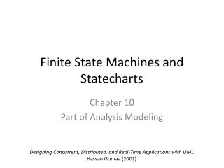
State Machines and Statecharts
390 likes | 537 Vues
State Machines and Statecharts. Shmuel Katz The Technion. Formal Specifications CS236368. Gestalt.

State Machines and Statecharts
E N D
Presentation Transcript
State Machines and Statecharts Shmuel Katz The Technion Formal Specifications CS236368
Gestalt Gestalt psychology or gestaltism (German: – "essence or shape of an entity's complete form") is a theory of mind and brain of the Berlin School; the operational principle of gestalt psychology is that the brain is holistic, parallel, and analog, with self-organizing tendencies. The principle maintains that the human eye sees objects in their entirety before perceiving their individual parts. Gestalt psychologists stipulate that perception is the product of complex interactions among various stimuli. The gestalt effect is the form-generating capability of our senses, particularly with respect to the visual recognition of figures and whole forms instead of just a collection of simple lines and curves. In psychology, gestaltism is often opposed to structuralism. The phrase "The whole is greater than the sum of the parts" is often used when explaining gestalt theory.
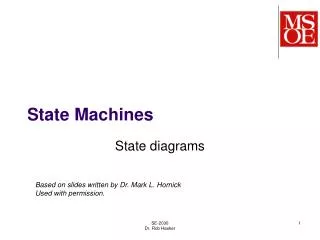
What is a State? • A snapshot of the system x = 17 y = 0 z = 8 • Set of values for variables light_on alarm_off • Control location(s) msg = “abc” • Contents of channels • May be written as a tuple (x=17, y=0, z=8)
A Simple State Machine An abstract watch: p state date time p initial state rem insert rem transition battery-off
What if the state is complex? • Write values of variables in the state • For every possible combination of values, there is a different state • Alternative terms: • State Machine Graph • State Transition Graph • Explicit State Graph • Paths in the graph = Traces = Executions x = 17 y = 0 z = 8 x = 17 y = 7 z= 3
Execution sequences • State view: < time, date, time, date, bat-off, time > • Transition view: < p, p, p, rem, insert > p date time p rem insert rem battery-off
Formal Definition • A state machine is a 4-tuple (S, A, I, T) with • S : set of possible states • A: set of possible labels on transitions • I : set of initial states (subset of S) • T : transition relation over S x A x S • (s1, a, s2) is in T when • T is a relation because of nondeterminism a s1 s2 a s2 s1 s3 a
Example • S = { time, date, bat-off } • A = { p, rem, insert } • I = { time } • T = { (time, p, date) , (date, p, time) , (time, rem, bat-off) ,(date, rem, bat-off), (bat-off, insert, time) }
State Machines Are Used! • When it is easy to abstract away irrelevant details, leaving only a small number of states • When we want to precisely examine every possibility using model checking • For communication protocols and complex distributed algorithms (EFT, ....) • For safety critical, or firmware that can’t be changed later
The State Explosion Problem • State machines can get huge for very simple systems • Need a more compact representation! • Describe the set of states from which a transition appears through a predicate • Describe the `target’ through the changes from the source • Use text and not pictures
Z describes State machines! • A collection of operation schemas, with explicit preconditions, can be seen as a state machine representation • There are many other notations, that mainly treat concurrency • To generate explicit version from schema, start from initial states, apply relevant operations. Repeat until nothing is added (a fixed point is reached).
A Z State Machine • P == [ st, st’ | st = time or st = date and (st = time) => st’ = date and (st = date) => st’ = time ] • rem ==[ st, st’ | (st = time or st = date ) and (st’ = bat-off) ] • insert ==[ st, st’ | st = bat-off and (st’ = time) ] • new == [st’ | st’ = time ]
Hints on translating • Can do one-to one translation, • gather the arrows that correspond to a single label into a schema with the name of the label • preconditions are union of the source states • predicate has source => target’ for each arrow • Can often combine into general predicates and state transformations • Explicit graph means a different state for every possible combination of values
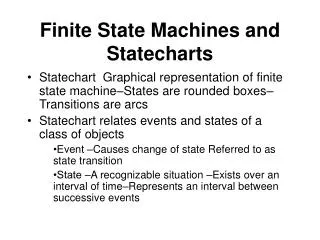
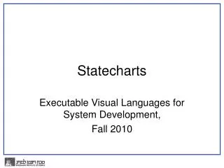
Statecharts • Graphic state machine representation • Compact--- avoids state explosion • Uses zoom-in, zoom-out • Separates concerns • By David Harel, while consulting for industry (avionics)
Causes of clutter • Pulling eject lever leads to a special situation (many arrows, can double the number of states) • Changing gears and adjusting the lights are independent of each other (multiplies the number of states describing gears by the number describing light settings) • There is a time display updated every 0.1 second, and a similar stopwatch display
Overcoming the Problems • Group states into Superstates that can be entered or left under uniform conditions • Keep independent parts separate-- do not take the cross product • Hide and separate out most values of variables • Keep `activities’ and data manipulation outside the statecharts
Superstate (without parallel) • Composed of a lower level statechart • in S == in time or in date • In a superstate => in one of its substates • Arrow from boundary = arrow from each (top level) interior state • Still can have direct exit from a state rem time battery-off p p insert date
How to Enter • Arrow to the boundary, and enter the default state (denoted by a short arrow) • Direct to an inner state • Unspecified at this level time p p date time p p date time p p date
More details on transitions • Form: name [ cond ] / action • Only do the transition if the cond holds • Do the indicated action as a side effect • Actions can include • Updating a variable • sending a message • starting or stopping an external “activity” • Output • Conditional entrance to targets (and the alternatives have predicates) C
A Statechart for Power Failure mode p normal reconfig long_p toolbox p done alternate p p / record test warm_start EPF (not in (test)) (in (test)) C done take_down battery cold_start power_up power_off/ mode := ‘stop’ EPF
Parallel Processes • For describing independent components • Dotted lines between statecharts, each with a default • in S == in each component of S • arrow to boundary == enter each default • Arrow from boundary == leave all components • Can have multi-headed or -tailed arrows
Transitions in Parallel Components • Transitions are used to `coordinate’ components when needed • Recall: name [ cond ] / action • Conditions can include being in a certain state in a parallel component • Actions can include • Updating a variable • sending a message • starting or stopping an activity • output • activating a transition in a parallel component
Joint Transitions If in A and in C, s is a joint transition to (B,D), but if in A and in D, s just does A->B If in E and in B, t does E->F, otherwise nothing happens when t ‘occurs’ C E A t [in B] s s D F B
Parallel “means” Almost Independent security mode total_kw_cum regdisp normal displayable p done p alternate (in (regdisp)) (not in (regdisp)) long_p p toolbox p hidden test
Two Equivalent Statecharts B,F h k E g B,G k B,E B e = f F e g e f [in G] e g h C,G C C,E G e e C,F k h
Mini-steps in Transitions • An action can be to activate another transition (from a parallel component). e / f could mean that transition e activates f, so both occur in the same step.... In UML version: e now activates f in the next step --avoids problems (`chain-reactions’ or even cycles) If only f occurs, there is no influence in the other direction.
History • H (in a circle) means the state from which the superstate was last exited is `remembered’, and an arrow from outside to the H returns the superstate to the one last left (on the uppermost level) • H* as above, but to lowest level of nesting • (Warning: different tools use H differently—so check what happens in the one you use…) • clh = `clear history’ A special action that erases the history, so the default is used for the next entry.
An Example: David Harel’s Watch Citizen Quartz multi-alarm III alarm1 - status chime - status light main disabled disabled off d (in alarm1. on) d (in alarm1. off) d (in chime. on) d (in chime. off) batt. inserted b -b decd enabled enabled on batt.removed /clh(main*) alarms – beep displays quiet power alarm 2 - status T is whole hour 2 sec in beep disabled OK beep bat. weakens d (in alarm2. on) d (in alarm2. off) weak batt. dies /clh(main*) blink enabled
Zooming in on Displays in the watch displays H* 2 sec in wait wait date c d update c d time b 2 min. in date a a a a a alarm 1 stopwatch chime alarm 2 H H H off off off d d d d d d on on on b c c b update 2 update 1
Tools • Statemate, from I-Logix, uses statecharts as the basic design/specification notation, adds activities and module decomposition separately, emphasizes simulation • Rhapsody, from I-Logix, and Rose, from Rational (both now inside IBM), incorporate statecharts into UML tools, for design level • All UML tools have drawing capabilities, only a few have simulations
Scenarios • Statemate gives feedback to clients through its simulation facility. • When can a beep occur? • If in states....we press d and then b without letting go, what will happen? • Where does an action have an effect? • Can `test’ use-case scenarios and `debug’ the specification relative to client needs
Activities of Statemate • Defined outside statecharts, ongoing and sustained over time. Each activity A has associated actions: • start(A) • stop(A) • suspend(A) • resume(A) • and a condition active(A) • and events that can trigger transitions: • started(A) • stopped(A) • Can also link an activity to being in a state
Object Oriented Statecharts • In UML, Statecharts describe internal behavior of objects, while sequence charts show scenarios of message calls among different objects • Activations are usually message calls, and follow usual rules of delayed activation, and even queueing: different from original • Different versions have somewhat different rules for ordering/synchronizing—see tirgul • Less use of parallelism than in pure statecharts
Guard Conditions • Act as preconditions
Statecharts: referring to states • The operation oclInState returns true if the object is in the specified state.—gives ‘in’ used previously • object.oclInState( statename )
Fuzzy parts • Real-time will be treated later • Updating the variables is `behind the scenes’ and not handled very well in Statecharts • Note that in the watch statechart, the actual time is not treated! • Connections to other notations (e.g., more informal UML parts) is so-so
Summary on Statecharts • A graphic notation: visual/Gestalt • The precision of automata, without the clutter • For precise design of key/complex protocols • For control and modes of operation—not data manipulation • Seems lower-level (assembly language of formal specifications?) • First mention of parallel---for (almost) independent components • Debug using simulation of use cases • Can sometimes synthesize into code skeletons