Download

1 / 26
260 likes | 376 Vues
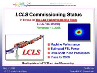
Near term opportunities for LCLS 'upgrades' . ge x,y = 0.4 m m (slice) I pk = 3.0 kA s E / E = 0.01% (slice). Recent Results! (25 of 33 undulators installed). J. Hastings for the LCLS Experimental Facilities Division June 25, 2009. Goals. Increase user access Multiplex options

E N D
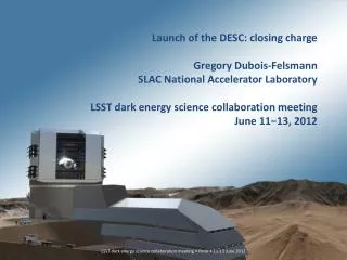
Near term opportunities for LCLS 'upgrades' gex,y = 0.4 mm (slice) Ipk = 3.0 kA sE/E = 0.01% (slice) Recent Results! (25 of 33 undulators installed) J. Hastings for the LCLS Experimental Facilities DivisionJune 25, 2009
Goals • Increase user access • Multiplex options • Soft x-rays (800-2000eV) - AMO, SXR • Hard x-rays (up to 25 keV) – XPP, XCS, CXI, MEC • Performance enhancements • Energy range • Long wavelength • Short wavelength • Polarization • Pulse duration • Laser-electron beam interactions
CXI X-ray transport tunnel XCS XPP MEC SXR XCS Offset Monochromator AMO
AMO, SXR, XPP, XCS, CXI, MEC Soft X-ray mirrors AMO SXR Hard X-ray mirrors Large offset monchromator Instrument layout
Soft X-ray experiments at LCLS Soft X-Ray Offset mirror system Typical AMO experiments are dilute samples: put re-focusing optics behind AMO: run two experiments in ‘parallel’ (500) 800 eV – 2 keV Beam sharing in place on a ‘12 hour basis’ (mirror deflection between AMO and SXR)
XCS Large Offset Monochromator Troika, ID10B, ESRF Kohzu, BL24XU, Spring-8 LUSI Concept
Baseline: • K = 3.5 • = 3.0 cm • = 8415 (4.3 GeV) 1=1.5 nm • Long wavelength ‘limit’: • K = 3.5 • = 3.0 cm • = 5870 (3.0 GeV) 1=3.1 nm lu lu Long wavelength limit
Si (111) 0.75-Å 1.5-Å 2nd Harmonic Afterburner Increase hard x-ray energy reach 1.5-Å LCLS Undulator afterburner 130 m 43 m 0.75-Å radiation using “spent” LCLS beam, and completely parasitic to LCLS operation at 1.5 Å. Add 40-m, 2nd-harmonic tapered undulator SLAC-PUB-10694. 0.75-Å Parameters: Z. Huang, S. Reiche
Polarization Control by Crossed Undulator • Horizontal + vertical undulators or two helical undulators • Polarization controlled by phase shifter, fast switch possible with pulsed dipoles at ~100 Hz -π/2 π/4 -π/4 0 Ex + Ey Phase shifter π 5π/4 π/2 π/2 • Studies show that equal power in x & y requires L2 = 1.3LG • Over 80% polarization is expected at SASE saturation • Second undulator can be adjusted as a second-harmonic afterburner if needed K.-J. Kim, NIMA 2000 Y. Ding & Z. Huang,PRST-AB 2008
Thin slotted foil in center of chicane coulomb scattered e- e- unspoiled e- coulomb scattered e- 15-mm thick Be foil PRL92, 074801 (2004). y P. Emma, M. Cornacchia, K. Bane, Z. Huang, H. Schlarb, G. Stupakov, D. Walz (SLAC) 2Dx x DE/E t
2 fs fwhm z 60 m Genesis 1.3 FEL code ~1010 photons x-ray Power (<1 fs possible) Power (GW)
SIMULATED FEL PULSES Y. Ding Z. Huang 1.5 Å, 3.61011 photons Ipk = 4.8 kA ge 0.4 µm Simulation at 1.5 Å based on measured injector & linac beam & Elegant tracking,with CSR, at 20 pC. Y. Ding Z. Huang 15 Å, 2.41011 photons, Ipk = 2.6 kA, ge 0.4 µm 20 pC tested J. Frisch 1.2 fs time-slicing at 20 pC Simulation at 15 Å based on measured injector & linac beam & Elegant tracking,with CSR & 20 pC. Measurements and Simulations:20-pC Bunch, 14 GeV MEASURED SLICE EMITTANCE 135 MeV 20 pC gex = 0.14 µm accepted in PRL
Power profile at 25 m Average photon number: 2.4x10¹¹ Estimated time-bandwidth product ~ 3 times Fourier-transform limit.
30 fs Two-Stage SASE FEL Self-seeding Short pulse, or narrow bandwidth, & wavelength is more stable Moderate – new undulator line or upgrade SLAC-PUB-9370, TESLA-FEL-97-06E, SLAC-PUB-9633, SLAC-PUB-10310 30 Parameters: C. Pellegrini
Measuring Bunch Arrival Time Jitter with an RF Deflector V(t) BPM Y Position (mm) TCAV OFF TCAV ON 9 mm rms 110 mm rms Dt±0.6 ps e- S-band (2856 MHz) y-BPM slope = -2.34 mm/deg Now measure BPM jitter with deflector OFF, and then ON (at constant phase) Timing Jitter = (110 mm)/(2.34 mm/deg) = 0.047 deg 46 fsec rms
short pulse train 800-nm modulation (few GW) 24 kA 15-25 kA peak current enhanced x7 70 as Peak current z /lL SASE FEL 4 GeV 14 GeV Allows synchronization between laser pulse and x-ray pulse E-SASE(applied to LCLS) A. Zholents PRL
ESASE in the LCLS Chicane buncher R56 = 0.3-0.8 mm 10-GW laser L = 0.8-2.2 m wiggler ~3 m 10-period 4.54 GeV z 0.02 mm rf gun rf gun Linac-1 L 9 m rf -25° Linac-2 L 330 m rf -41° Linac-3 L 550 m rf -10° 13.6 GeV new Linac-0 L 6 m Linac-1 BC1 Linac-2 BC2 Linac-3 Linac-0 undulator L 130 m undulator L 130 m X X …existing linac …existing linac BC1 R5639 mm BC2 R5625 mm DL2 Laser Heater Laser Heater DL2 R560 DL1 R56-6 mm SLAC linac tunnel undulator hall New elements
ESASE single spike selection • Two ten-cycle lasers (second laser tunable wavelength with OPA) • Tapered undulator to compensate LSC and enhance contrast E (MeV) P(GW) Ding, Huang, Ratner, Bucksbaum, Merdji, FEL2008
Special Thanks to: Y. Ding, P. Emma, J. Frisch,Z. Huang, H. Loos, A. Zholents, J. Wu ……