Download
1 / 42
420 likes | 567 Vues
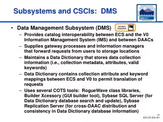
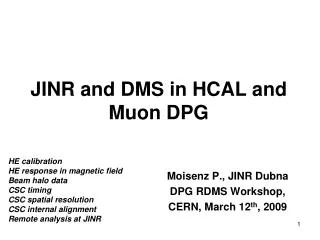
JINR and DMS in HCAL and Muon DPG. Moisenz P., JINR Dubna DPG RDMS Workshop, CERN, March 12 th , 2009. HE calibration HE response in magnetic field Beam halo data CSC timing CSC spatial resolution CSC internal alignment Remote analysis at JINR. HE calibration for the 1 st LHC day.

E N D
JINR and DMS in HCAL and Muon DPG Moisenz P., JINR Dubna DPG RDMS Workshop, CERN, March 12th, 2009 HE calibration HE response in magnetic field Beam halo data CSC timing CSC spatial resolution CSC internal alignment Remote analysis at JINR
HE calibration for the 1st LHC day HE Calibration with Combined ES/EE/HE Data (TB07) Introduction ES, EE, HE calibration Beam cleaning Particle identification Absolute energy scale Uniformity scan Sourcing Cosmic runs analysis Beam halo Magnetic field Spatial resolution Conclusion P. Moisenz (JINR, Dubna, Russia), RDMS Conf. 14-19 Sept. 2008, Minsk (Belarus)
Introduction • Muon energy scan for HE, ES • Energy scan from 2 GeV up to 300 GeV (pion and electron for HE, EE+HE, ES+EE+HE) • Spatial resolution scan for HE • Uniformity scan for ES+EE+HE • Sourcing EE back plane
Test Beam 07 HE EE ES BEAM Freon CO2
HE L3 Calibration Ebeam for e beam Ebeam·π/e for π beam 1+(e/h-1)·α·log(Ebeam) π/e= e/h 44 cal. coeff. from calib. region • e/h and α are from • a priori knowledge of detector • simulation • experimental data · · · · • pions from 20GeV up to 300GeV • electrons from 20GeV up to 150GeV • total number of showers is ≈ 260000 HE prototype
HE Standalone Absolute Energy Scale (η=19.5, φ=14.5 ) Linearity from energy correction Energy resolution from π/e energy correction
HE Combine Absolute Energy Scale (η=19.5, φ=14.5 ) EE<1GeV (mip) EE≥1GeV (mip)
HE gains with Sourcing AW/AC ratio vs η for 4th layer (φ=3) Source Purchase Original (Co-60) Date Activity RP4171 Dec 2005 186MBq HE+ sourcing Feb 2006 RP4168 Dec 2005 146MBq TB07 sourcing Mean value of TB07 sourcing (with collimated source normalization) is .2338fC. In Feb 2006 RP4168 had 21.5/5.271*.2338=.2848fC. With RP4171 normalization .2848*186/146=.3628fC. In normal mode - .3628/3=.1209fC or .1209fC*.19345GeV/fC=.0234GeV Vardan Khachatryan HE gains distribution with TB07 data
Muon Energy Deposition (TB07 vs CRAFT08) TB07 CRAFT08 2.859·.88=2.516GeV 2.656·cos(η=1.603)=2.449GeV Due to track slope Due to π- (50GeV) calibration
HE Response in Magnetic field STUDY OF MAGNETIC FIELD INFLUENCE ON HE RESPONSE(CRAFT ReReco Data) Moisenz P., Khachatryan V. JINR, Dubna, DPG meeting, February 23th, 2009 Introduction CRAFT Rereco Data Conclusion
New CRAFT Data (ReReco) TRACKER ME1/1 CRAFT Reco CRAFT ReReco For CRAFT Data (ReReco) we have - new individual (π 50GeV) HE calibrations both for B=0T and B=3.8T with factor 1.08 - new tracker software - new CSC alignment
CRAFT: Software Trigger • Two segments from CSC stations as minimum (ME1/1 +some other) • Track is in tracker • Signals from HE track association towers • 17≤HETOWER≤29 • 60≤Track Slope ≤ 500 • Momentum ≥ 7GeV • Track intersects front/backplane of HE • For 0T track is in CSCs and DTs ME1/1 CT HE CMSSW_2_2_3 /Cosmics/Commissioning08_CRAFT_ALL_V4_ReReco-v1/RECO NZS mode
CRAFT: HE- Data B=3.8T B=0T
CRAFT: HE Signal vs Magnetic Field E(3.8T)/E(0T) vs Energy cut Due to tick of layer 0 1.00327x1.08=1.0835 (±.0125) CMS magnetic field (3.8T) increases scintilator brightening up to 8.35 (±.0125) %
Plans • CRAFT08 Re-reprocessing data analysis • CRAFT09 data analysis (Traker+ES+HE) • HE calibration testing with CSC data • HE timing (?) • Simulation
Beam Halo Data and CSC Timing HE and EMU Combined Operation ( Beam Halo data) Vladimir Karjavin Peter Moisenz Alexey Kamenev Vardan Khachatryan CSC DPG+Commissioning meeting, 16 October, 2008, CERN • Introduction • •HE Energy deposition • • ME timing study with HE response • Conclusion
1st Beam Halo Signals in HE • Software Muon Trigger from CSC • Two segments from CSC stations as minimum (ME1/1 +some other) • Signals from HE towers associated track • 17≤HETOWER≤29 • Track Slope ≤50
Beam Halo Signals in CSCsCSC Rechits (belong to tracks) distribution Asymmetry in x, y axis All CSC ME1/1 is active
Beam Halo Signals in CSCs Track Slope Distribution Beam halo tracks “source” distance: z≈-56m 56m is here
Beam Halo Signals in HEHE Energy Deposition HE energy deposition associated with CSC tracks
HE Energy Deposition with Beam Halo Data TB07 µ 225GeV Rechits collection criteria: HE towers associated with CSC track Good matching of the Beam test results
HE Timing from Splash Events HE- HE+ J. Damgov
Raw Signal from HE Towers (sum in 10 time slices) Cut for muons = 8ADC Single tower has muon signal if sum of amplitudes (in 0÷9 time slices) >8ADC
Summary • HE energy deposition associated with CSC tracks: • good matching of the results obtained with Beam test and Beam halo data • Analysis of ME timing with Beam Halo tracks shows: • timing distribution (mean value) from all ME stations: ~ 1BX • possibility of precise time calibration of ME chambers
CSC Spatial resolution ME1/1b, ME2/1 and ME3/1 Spatial Resolutionfrom CRAFT data Vladimir Palichik, Peter Moissenz, Dubna, JINR CSC DPG meeting March 05, 2009
ME1/1b, ME2/1 & ME3/1 Spatial Resolution from CRAFT data • 4 methods to estimate CSC resolution: • Studentized residuals between a strip hit coordinate in the plane and the fitted track coordinate in this plane from a straight line uniformly precise6-point fit (is used for ME1/1b; is not convenient for ME2 & ME3 due to strip staggering) • Residuals between a strip hit coordinate in the 3rd (4th ) plane and the predicted track coordinate in this plane from a straight line fit of hits in the remaining 5 planes • c2 distributions for Residual Sum of Squares (RSS) for all 6 hits line fit (as it was shown at the meeting on 29.01.09, the results obtained were underestimated) • Two independent (separate) 3-point fits in two strip regions (see page 7)
ME1/1b Resolution from CRAFT In comparison to the results presented at CMS Week in Dec.2008 we use the more soft thresholds forc2-criteria Method I ME1/1b Spatial Resolution after additional cross-talk corrections (see 08.12.08 report at CMS Week) ME1/1b • (ME1/1b) = 112 mm per Layer i.e.: s = 1.87 % of strip width • (ME1/1b) ~ 50-55 mm per Station Resolution versus Radius
ME2/1 Residuals from CRAFT for 2 regions across a strip width Method II (shown 29.01.09) 1/s2 (Station) = 3/s12 + 3/s22 As in CMS NOTE 2007/023, V.Barashko et al. s (ME2/1) = 166 mm s1 = 328 mm Strip region 0.25-0.5 (strip edges) Strip region 0-0.25 (strip center) Similar results have been obtained for ME3/1 s2= 580 mm
ME2/1 Studentized Residuals for 2 regions across a strip width Method IV Strip region 0.25 - 0.5 (strip edges) Strip region 0 - 0.25 (strip center) s1 = 252 mm s2= 560 mm Si – square of i-th Gaussian sk2 = s1 /(s1 + s2) * sg12 +s2 /(s1 + s2) * sg22 1/s2 (Station) = 3/s12 + 3/s22 s (ME2/1) = 133 mm The similar results have been obtained for ME3/1: s (ME3/1) = 126 mm
Conclusions: ME1/1b The satisfied ME1/1b single layer spatial resolution (112 microns) has been obtained from CRAFT data with 3.8 T magnetic field in CMSSW_2_2_0 (several improvements with additional cross-talk corrections) applying the more soft Chi2 cuts (in comparison with Dec.08 CMS Week report); studentized residuals have been used. Thus, ME1/1 outer part spatial resolution per station could be estimated approximately as 50-55 microns. There are still problems with estimation of ME1/1 inner part resolution due to strip ganging.
Conclusions: ME2/1 & ME3/1 • 2 methods (II-nd and IV-th) have been used to estimate spatial resolution in the ME2/1 & ME3/1 stations from CRAFT data with 3.8 T magnetic field in CMSSW_2_2_0 : • II) Residuals between a strip hit coordinate in the 3rd (4th ) plane and the predicted track coordinate in this plane from a straight line fit of hits in the remaining 5 planes: • s(ME2/1 station) = 166 microns • s(ME3/1 station) = 176 microns • IV) Two 3-point fits in central & edge strip regions separately with studentized residuals: • s(ME2/1 station) = 133 microns s(ME3/1 station) = 126 microns • Plan • CSC spatial resolution with uncorrelated background We suppose these results are overestimated
CSC Internal alignment ME1/1 internal alignment with MTCC data (status and plans) I. Belotelov, A. Kamenev, P. Moisenz (JINR, Dubna), EMU ME1/1 Meeting, 16.06.07, CERN
Outer layer fix: method details • Select segments with 2 rec hit in outerlayers • Construct the straight line using these 2outer hits • Collect the residuals in 4 inner layers. • For misalignment studies, residuals arecollected to 10 histograms per layer (10ρ-slices per each layer) • each ρ-slice fitted by gaussian to estimate its shift • all shifts of ρ-slices in layer then fittedby straight line - it gives layer φ-shiftand rotation around z
Outer layer fix: layer shift distribution vs MF • Layer shifts up to 100 of microns, few layers shifted by > 200 microns • There are clearly detectable -rotations • Good correspondence with K. Banicz (MTCC) and A. Korytov (FAST sites) results (CSC DPG Meeting, CERN 15.03.07) • Depending on the selection and track model (polar or cartesian) overall shift forB-on runs sometimes 10-15 microns bigger than for B-off runs.
LSQ track fit:coordinate system The local reference frame XY of each layer is rotated by angle α and than shifted in general reference frame XY. So internal alignment parameters are angle α and shifts Dx and Dy.
LSQ track fit:formalism Here are some formulas: - functional for best track building - distance between layers - best track hits - alignment functional Shifts expressed through rotation angle - set of equations, to be solved - notation example - equation for the rotation angle
LSQ track fit: alignment parameters vs magnetic field Here are the shifts and rotations for all the 6 layers of all the 6 CSCs for magnetic field 2T, 3.8T, 4T relative the shifts and rotations at 0T.There is no evident dependence.
Conclusion • Internal alignment parameters of ME1/1 CSCs from MTCC data were calculated • There is no evident dependence of alignment parameters from magnetic field • Plan • Internal alignment parameters stability from MTCC up to CRAFT • Internal parameters for all CSCs
Remote Analysis at JINR • Monitoring and Analysis Remote System • Remote monitoring of ME1/1 and HE • Express analysis • DQM • Shifts • MARS hardware • Server (6TB) • 3 PC (3x.5TB) • 6 (6x.5TB) remote points for physicists (with afs)