Channel Design
450 likes | 611 Vues
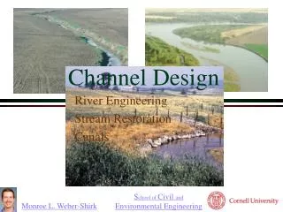
Channel Design. River Engineering Stream Restoration Canals. References. Chapter 12 Stable Channel Design Functions in the HEC-RAS Hydraulic Reference

Channel Design
E N D
Presentation Transcript
Channel Design River Engineering Stream Restoration Canals
References • Chapter 12 Stable Channel Design Functions in the HEC-RAS Hydraulic Reference • FISRWG (10/1998). Stream Corridor Restoration: Principles, Processes, and Practices. By the Federal Interagency Stream Restoration Working Group (FISRWG) • Chapter 4 in Water Resources Engineering by David Chin (2000)
Outline • Sediment transport • Effects • Suspended and Bed load • Stable unlined channel design • Tractive Force method • Bed forms • Channel forms • River Training • Stream Restoration Principles
Problems of Sediment Transport • Impingement of Sediment Particles • damage to bridge abutments by boulders • huge boulders (up to several tons) can be set in motion by torrential flood flows in mountain streams • sand-sized particles damage turbines and pumps • Sediment in Suspension • fish don’t like muddy water • municipal water treatment costs are related to amount of sediment in the water
Problems of Sediment Deposition • irrigation ditches • reduce carrying capacity • require extensive maintenance • drainage ditches • raise the water table • fine sediments are usually fertile - increase vegetation growth - increase Manning n • Flood Plain Deposits • may bury crops • deposition of infertile material (like sand) may reduce fertility • Urban areas may receive deposition on streets, railroads, and in buildings
Problems of Sediment Deposition • channels, waterways, and harbors • requires extensive dredging to maintain navigation • decrease carrying capacity and thus increase flooding • lakes and reservoirs • in lakes with no outlets all of the incoming sediment is deposited • converts beaches to mud flats • fine sediment can encourage prolific plan growth • storage capacity is lost • by 1973 10% of reservoirs built prior to 1935 in the Great Plain states and the Southeast had lost all usable storage!
Sediment Load • Mass of sediment carried per unit time by a channel • Sediment load is carried by two mechanisms • Bed load: grains roll along the bed with occasional jumps • primarily course material • Suspended load: material maintained in suspension by the _________ of flowing water • primarily fine material turbulence
Suspended Load • Sediment suspended by fluid turbulence • Concentration can be substantial in cases of high flows and fine sediment (up to 60% by weight!) • Vertical distribution • higher concentration near bottom • coarse fractions - concentration decreases rapidly above bed • fine fractions - concentration may be nearly uniform • no theory for concentration at the interface with the bed • given sediment concentration at one elevation above the bed it is possible to derive sediment concentration as a function of depth (compare local fall velocity with local turbulent transport)
Suspended SedimentUpward Transport z upward transport is due to diffusion flux (Fick’s first law) The diffusion coefficient is a function of depth! D D = Velocity * Distance Dt k = von Kármán’s universal constant k = 0.4 for clear fluids
Suspended SedimentConcentration Profile at steady state we have: upward transport = downward transport where boundary condition: c = ca @ z = a by convention: a = 0.05h sedimentation velocity Result after integration
Suspended Sediment Equilibrium Profile Why? z 1 0.8 D 0.6 Depth/D 0.4 v 0.2 a Dt 0 0 5 10 15 20 sediment concentration
Bed Load • Dependent on • sediment size distribution • bed shape (ripples, dunes, etc.) • sediment density • shear stress at the bed • Bed Load Equations • many researchers have proposed equations • each equation only applies to the data that was used to obtain the equation!
Total Sediment Carrying Capacity • Power law relations between sediment flux (Js) and specific discharge (q) fit the data when the exponent (n) is between 2 and 3 • Consequences: • as q decreases Js decreases • abstraction of flow from a river • for irrigation, water supply or flood relief • sediment carrying capacity decreases • river channel tends to clog with sediment to reach new equilibrium • greatest transport of sediment occurs during floods • rivers below reservoirs tend to erode
Sediment Rating Curve: 10Q yields 100Js
Causes of Stream Erosion • What can increase the rate of erosion? • Increased stream flow • Increased runoff • Decreased flood plain storage • Decrease in sediment from upstream
Channel Geometry Channel Slope Cross section Roughness Meander Soil Grain size Cohesive/uncohesive Lining type Lined Unlined Grass Design Flow Bank full Or based on a recurrence interval Channel Design:Identify the Parameters
Stable Unlined Channel Design • Threshold of movement • Will determine minimum size of sediment that will be at rest • Can be used as basis for stable bed design • Based on Shield’s diagram • Modified to include the effect of side slope
Basic Mechanism of Bed Load Sediment Transport • drag force exerted by fluid flow on individual grains • retarding force exerted by the bed on grains at the interface • particle moves when resultant passes through (or above) point of support V h force of drag will vary with time Fd Fg Grains: usually we mean incoherent sands, gravels, and silt, but also sometimes we include cohesive soils (clays) that form larger particles (aggregates) point of support
Threshold of Movement Force on particle due to gravity Force on particle due to shear stress Force balance We expect movement when dimensionless parameter
Shields Diagram (1936) inertial Re* _____________ = Shear Reynolds at the bed! viscous d = particle diameter 1 Suspension Saltation 0.1 0.056 Threshold of movement No movement 0.01 1 10 100 1000 Laminar flow of bed Turbulent flow of bed
Shear Velocity Bottom shear u* = shear velocity = From force balance turbulent Shear velocity is related to _________ velocity
Magnitude of Shear Velocity in a River • Example: moderately sloped river • Susquehanna at Binghamton • S = 10-4 • d =Rh= 1 m Manning Eq. (SI) units assume n of 0.03 Velocity fluctuations in rivers are typically _____ 0.1V
Application of Shield’s Diagram Find minimum particle size that will be at rest Often bed is turbulent quartz sediment Example (Susquehanna River at Binghamton) 1 m deep, S = 10-4 Therefore 1.1 mm diameter sand will be at rest. Result is “armoring” of river bed with large gravel as smaller sediment is flushed out.
Application to Channel Stability Assumed uniform shear stress distribution = max angle of repose 35° river max to prevent erosion of bottom
Channel Side Slope Stability • Takes into account the shear stress, force of gravity and coefficient of friction • Meandering (sinuous) canals scour more easily than straight canals (see Table 4.15 in Chin) Critical shear stress on the bed Critical shear stress on the side slope Side slope angle Tractive force ratio Angle of repose Ch 12 in HEC-RAS Hydraulic Reference
HEC-RAS Hydraulic Design: Stable Channel Design • Copeland* • Regime* • Tractive Force • Doesn’t account for input sediment • Utilizes critical shear stress to determine when bed motion begins • Particle size (d) • Depth (D) • Bottom Width (B) • Slope (S) • Uses shear stress and Manning equations Given any two can solve for the other two *Require input sediment discharge
Implications • How could you reduce erosion in a stream? • Are we managing causes or treating symptoms? Decrease slope Decrease depth (increase width or decrease flow) Increase particle size
stabilizing eroding channels upstream controlling erosion on the watershed installing sediment traps, ponds, or debris basins narrowing the channel, although a narrower channel might require more bank stabilization flow modification grade control measures other approaches that dissipate the energy Vertical Stabilizing Techniques Aggradation Degradation meanders boulders
Indirect methods extend into the stream channel and redirect the flow so that hydraulic forces at the channel boundary are reduced to a nonerosive level dikes (permeable and impermeable) flow deflectors such as bendway weirs, stream “barbs,” and Iowa vanes Surface armor Armor is a protective material in direct contact with the streambank Stone and other self-adjusting armor (sacks, blocks, rubble, etc.) Rigid armor (concrete, soil cement, grouted riprap, etc.) Flexible mattress (gabions, concrete blocks, etc.) Bank Stabilizing Techniques • Vegetative • can function as either armor or indirect protection and in some applications can function as both simultaneously.
Bed Formation • Variety of bed forms are possible • may be 3 dimensional • may vary greatly across a river or in the direction of flow • Bed forms depend on Froude number and affect ____________ • Bed forms result from scour and deposition • deposition occurs over the crests and scour occurs in the trough • Bed forms are the consequence of instability • a small disturbance on an initially flat bed can result in formation of crests and troughs roughness
Bed Forms low velocity, fine sediment sand wave moves down stream wavelength less than 15 cm Ripples, Fr << 1 weak boil intermediate between ripples and dunes Dunes with superposed ripples, Fr < 1 larger and more rounded than ripples boil Dunes, Fr < 1
Bed Forms (2) Dunes are eroded at Froude number close to 1 Note reduction in friction factor or Manning n! Flat bed, Fr = 1 Standing waves in phase with water waves Standing waves, Fr > 1 Sand waves move upstream wavelength is incipient breaking and moving upstream Antidunes, Fr >> 1
River Channels • Alluvial soils • river can form its own bed • river will meander in time and space • steep slopes • braided channel • intermediate slopes • riffle pool formation • mild slopes • meandering channel
Meandering Channel L rc B flow centerline scour surprisingly small variation!
Bed Forms in Meandering Channels Channel is deepest on the outside of the curves
River Training • Prevent shifting of river bed! • navigation • want the docks to be on the river! • flood control • want river to be between the levees! • bridges • want bridges to cross the river! • Canalize - straighten out meanders • cutoff meander - increases slope • increases erosion • deposition further downstream
Braided channel Former Oxbow Changes to Mississippi River Arkansas Mississippi Consequences?
River Training • Current practice - “Stabilize” in natural form • bank protection • rip-rap (armoring) • Groins (indirect)
Stream Corridor Condition Continuum • At one end of this continuum, conditions may be categorized as being natural, pristine, or unimpaired by human activities • At the other end of the continuum, stream corridor conditions may be considered severely altered or impaired
Stream aggradation—filling (rise in bed elevation overtime) Stream degradation—incision (drop in bed elevationover time) Streambank erosion Impaired aquatic, riparian, and terrestrial habitat Increased peak flood elevation Increased bank failure Lower water table levels Increase of fine sediment in the corridor Decrease of species diversity Impaired water quality Altered hydrology Common Impaired or Degraded Stream Corridor Conditions Stream Corridor Restoration: Principles, Processes, Practices p 227
Design of Open Channels • The objective is to determine channel shape that will carry the design flow • Reasonable cost • Limit erosion • Limit deposition • Efficient Hydraulic Section • Freeboard to prevent overtopping • Return to “natural state”
Most Efficient Hydraulic Sections • A section that gives maximum discharge for a specified flow area • Minimum perimeter per area • No frictional losses on the free surface • Analogy to pipe flow • Best hydraulic shapes • best • best with 2 sides • best with 3 sides
Why isn’t the most efficient hydraulic section the best design? Minimum area = least excavation only if top of channel is at grade Cost of liner Complexity of form work Erosion constraint - stability of side walls Freeboard is also required
Freeboard and Superelevation • Freeboard: vertical distance between the water surface at the design flow and the top of channel • Rational design could be based on wave height, risk of flows greater than design flow, and potential damage from overtopping • Empirical design – 0.5 m to 0.9 m • Superelevation at bends • T is top width • rc is radius of curvature of the centerline • Valid for rc > 3T