Feature-Based Design in a Distributed Collaborative Environment
This paper presents a framework for enabling feature-based design in distributed collaborative settings. It addresses challenges in Computer-Aided Design (CAD) systems concerning data consistency, expensive IT infrastructure, and long update times. The objectives include establishing a virtual environment for collaboration, optimizing information transmission, and integrating manufacturing analysis modules. The study delves into visualization and co-design activities, communication mechanisms, and remote invocation technologies to facilitate simultaneous co-modeling, enhancing the design process through effective collaboration.

Feature-Based Design in a Distributed Collaborative Environment
E N D
Presentation Transcript
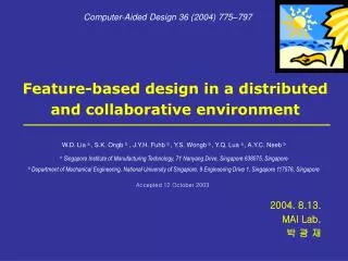
Computer-Aided Design 36 (2004) 775–797 Feature-based design in a distributed and collaborative environment W.D. Lia a , S.K. Ongb b, J.Y.H. Fuhb b , Y.S. Wongb b , Y.Q. Lua a , A.Y.C. Neeb b a Singapore Institute of Manufacturing Technology, 71 Nanyang Drive, Singapore 638075, Singapore b Department of Mechanical Engineering, National University of Singapore, 9 Engineering Drive 1, Singapore 117576, Singapore Accepted 12 October 2003 2004. 8.13. MAI Lab. 박 광 재
Contents • Introduction • Related work • System framework • Distributed feature-based representation and manipulations • Distributed and collaboration mechanisms • A Case study • Conclusions
Introduction • CAD systems are moving towards supporting distributed and collaborative design • Distributed CAD systems and methodologies have some practical issues ; • Expensive IT infrastructure • Difficulties in the maintenance of data consistency in a multiple-user environment • Long waiting-time for updating CAD models
Introduction • The objectives of this work are ; • (a) to establish a virtual environment to facilitate distributed and collaborative feature-based design activities • (b) to optimize the organization and transmission of information based on feature representation and manipulation • (c) to integrate downstream manufacturing analysis modules in an environment to support concurrent engineering design.
Visualization and annotation of 3D CAD model to assist co-design activities Related work Tool to assist co-design activities * STEP : Standard for the Exchange of Product model data(ISO 10303, ISO 9506) * IGES : Initial Graphics Exchange Standard(ISO 7942, ISO 9593, MIL-D-28000) * VRML : Virtual Reality Modeling Language * STL : Standard Template Library
Related work Example(SolidWorks eDrawing) View Zoom View Mark-up
viewer Manipulator Objects Comm. facilitators CAD system Modeling work space Client Client Client Client Server Message or CAD file Server viewer Manipulator Broadcast Sharing System Service CAD system Comm. facilitators Client Client Access & manipulate System Related work • Simultaneous co-modeling of 3D CAD model to implement real co-design • Some mechanisms for distributed modeling • Modeling client + communication server • Manipulation client + modeling server • Application or service sharing
Related work Co-design tool to share and manipulate real CAD models
Related work • Establishment of distributed CE environment to support co-design with manufacturing analysis and evaluation • COM interface-based framework to wrap and expose API functions of CAD kernels/systems • Process planning modules for remote invocations. • Standard interface specification • Manufacturing information through agent channels based on the Java RMI technology • Web-based design and manufacturing support systems * API : Application Program Interface * RMI : Remote Method Invocation
System frameworks • Main parts in the system • Design clients • A collaborative server • Downstream manufacturing modules • Event–driven communications • Remote interfaces of methods and objects exposed for remote calling in the environment • System framework consists of two primary aspects • Distributed feature representations and manipulations • Communication and collaborative mechanisms
System frameworks System framework of the distributed design environment
Distributed feature-based representation and manipulations • Distributed feature representations • Client side : A ‘light’ face-based representation • Server side : A ‘heavy’ representation with feature and part information • Data structures • Part Constructive Tree(PC_Tree) : hierarchical structure • Feature- to-Feature Graph(F2F_ Graph)
Structures of a part and its features on the server * B-REP : Boundary Representation
Distributed feature-based representation and manipulations • Feature manipulations • The working processes for modeling a part
Distributed feature-based representation and manipulations • Differentiation process for an added feature
Distributed feature-based representation and manipulations • Differentiation process for a deleted feature
Distributed feature-based representation and manipulations • Object event to wrap differentiated features
Distributed and collaborativemechanisms • Communication mechanisms for distributed design • Distributed design environment : Java RMI Remote interfaces in the distributed environment * RMI : Remote Method Invocation
Distributed and collaborativemechanisms • Mechanism for collaborative design • Process of carrying out a design task
Distributed and collaborativemechanisms • The control process of designing a part through a ‘control baton’
Distributed and collaborativemechanisms • Manufacturing analysis modules • CAPP optimization module • Methods : • Genetic Algorithm, Simulated Annealing, Tabu Search, hybrid Genetic Algorithm and Simulated Annealing • Activities : • selecting machining resources, determining setup plans, sequencing machining operations • Feature recognition module • manufacturability analysis module
A case study • Environment : JDK1.4, Open CASCADE 4.0 * JDK: Java Development Kit
A case study The percentages of reduction of the represented and transmitted information A1 = face-based representation/B-rep A2 = Added and Updated faces/face-based representation A3 = Added and Updated faces/B-rep
Conclusions • A distributed teamwork environment for 3D design can be built for practical usage • A manipulation method is used to facilitate efficient information exchange for large-size 3D models • High performance communications between a collaborative server and clients are maintained based on an event-driven mechanism • There are some technical problems to be addressed later • Multimedia communication functions • A web-based viewer based on a mesh simplification algorithm