Download
1 / 61
610 likes | 742 Vues
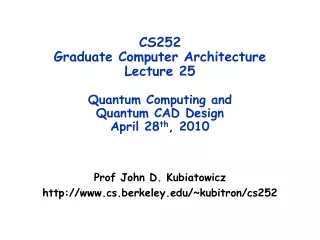
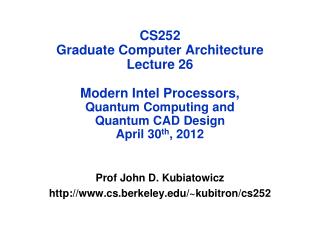
CS252 Graduate Computer Architecture Lecture 26 Modern Intel Processors, Quantum Computing and Quantum CAD Design April 30 th , 2012. Prof John D. Kubiatowicz http://www.cs.berkeley.edu/~kubitron/cs252. Intel’s Tock-Tick strategy. Typically, a new architecture is called a “tock”

E N D
CS252Graduate Computer ArchitectureLecture 26Modern Intel Processors,Quantum Computing andQuantum CAD DesignApril 30th, 2012 Prof John D. Kubiatowicz http://www.cs.berkeley.edu/~kubitron/cs252
Intel’s Tock-Tick strategy • Typically, a new architecture is called a “tock” • Major architectural changes appear here • A shrink of a “tock” in a new technology “tick” • Very few architectural changes appear here • Although there is at least one notable exception (Ivy Bridge) • Completely changed the GPU • A given technology often has at least a tick for an old architecture and a tock for a new architecture
Intel SandyBridge Processor • Some Core i3, i5, and i7 machines use this • But you need to look carefully to distinguish from Nahalem • Xeon (server) machines code-name “E5”
Chip-scale features of SandyBridge • Significant pieces: • Four OOO cores • New Advanced Vector eXtensions (256-bit FP) • AES instructions • Instructions to help with Galois-Field mult • 4 -ops/cycle • Integrated GPU • System Agent (Memory and Fast I/O) • Shared L3 cache divided in 4 banks • On-chip Ring bus network • Both coherent and non-coherent transactions • High-BW access to L3 Cache • Integrated I/O • Integrated memory controller (IMC) • Two independent channels of DDR3 DRAM • High-speed PCI-Express (for Graphics cards) • DMI Connection to SouthBridge (PCH)
Fetch and Branch Prediction • x86 instructions turned into micro-ops • Cached translations are reused • Branch prediction • Not entirely clear, but seems to have some combination of bi-mode, multi-level BTB, stack-based prediction for CALL/RETURN • Predecoder • Finds instruction boundaries • Passes at least 6 instructions onto decoding infrastructure
op decoders: Turn CISC RISC • CISC instructions translated into ops • Simple instructions turn into 1 – 4 ops • Complex instructions turned into stream of ops • Macro-Fusion: certain pairs of CISC Iinstructionsfused into single op • Micro-Fusion: certain pairs of ops turned into a single op • Branch Misprediction recovery: • ops cached for quick recovery from branch mispredictions • Pipeline can start executing ops immediately after branch misprediction – without waiting for old ops to clear
Explict Renaming to large PRFs • Decoder Queue • feeds 4 ops/cycle to ROB from one hyperthread • Can hold small loops • ROB helps with renaming/reordering • Commit of 4 ops/cycle done by updating rename freelist • Architecture differs from Nahalem • Nahalem stored values back into ROB (did not have explicit renaming) • Deemed too expensive in energy with large values moving around from AVX (lots of 128bit values)
Out-of-Order execution • Unified Reservation Unit • Full OOO execution • Pick 6 ready ops/cycle • Can have two loads or stores/cycle • 2 address generation units (AGUs) + store data • Simultaneous 256-bit Multiply and Add • Can have 3 regular integer ops/cycle 54 Entry Unified Scheduler
SandyBridge GPU • 12 shader engines that operate at 1/3 CPU frequency • Each can generate 8 single-precision FP ops/cycle • 96 FP ops/GPU cycle 109 gigaflops for CPU @ 3.4 GHz • Fixed function units for common tasks • Texturing, vertex processing, rasterization, Z-buffering • Multi-format codec engine • Video decoding for MPEG, VC1, and H.264 AVC up to 1080p • Hardware video encoding
SandyBridge I/O: PCH • Platform Controller Hub • Used to be “SouthBridge,” but no “NorthBridge” now • Connected to processor with proprietary bus • Direct Media Interface • Code name “Cougar Point” for SandyBridge processors • Types of I/O on PCH: • USB • Ethernet • Audio • BIOS support • More PCI Express (lower speed than on Processor) • Sata (for Disks) SandyBridge System Configuration
SandyBridge die photo • Package: LGA 1155 • 1155 pins • 95W design envelope • Cache: • L1: 32K Inst, 32K Data (3 clock access) • L2: 256K (8 clock access) • Shared L3: 3MB – 20MB (not out yet) • Transistor count: • 504 Million (2 cores, 3MB L3) • 2.27 Billion (8 cores, 20MB L3) • Note that ring bus is on high metal layers – above the Shared L3 Cache
Administrivia • Project Oral reports Friday 5/4 • Time: 1:00-4:00 • Place: Here (hopefully!) • Everyone must attend all of the time • Plan on a 15 minute talk with 5 minutes of questions • Submit your talk to your project page • Last chance to get changes to your midterm: Friday 5/4 • Final project paper due Monday 5/7 • Due by 11:59pm • Submit your paper to your project link
Use Quantum Mechanics to Compute? • Weird but useful properties of quantum mechanics: • Quantization: Only certain values or orbits are good • Remember orbitals from chemistry??? • Superposition: Schizophrenic physical elements don’t quite know whether they are one thing or another • All existing digital abstractions try to eliminate QM • Transistors/Gates designed with classical behavior • Binary abstraction: a “1” is a “1” and a “0” is a “0” • Quantum Computing: Use of Quantization and Superposition to compute. • Interesting results: • Shor’s algorithm: factors in polynomial time! • Grover’s algorithm: Finds items in unsorted database in time proportional to square-root of n. • Materials simulation: exponential classically, linear-time QM
North South Quantization: Use of “Spin” • Particles like Protons have an intrinsic “Spin” when defined with respect to an external magnetic field • Quantum effect gives “1” and “0”: • Either spin is “UP” or “DOWN” nothing between Representation: |0> or |1> Spin ½ particle: (Proton/Electron)
Kane Proposal II (First one didn’t quite work) • Bits Represented by combination of proton/electron spin • Operations performed by manipulating control gates • Complex sequences of pulses perform NMR-like operations • Temperature < 1° Kelvin! Single Spin Control Gates Inter-bit Control Gates Phosphorus Impurity Atoms
Now add Superposition! • The bit can be in a combination of “1” and “0”: • Written as: = C0|0> + C1|1> • The C’s are complex numbers! • Important Constraint: |C0|2 + |C1|2 =1 • If measure bit to see what looks like, • With probability |C0|2 we will find |0> (say “UP”) • With probability |C1|2 we will find |1> (say “DOWN”) • Is this a real effect? Options: • This is just statistical – given a large number of protons, a fraction of them (|C0|2 ) are “UP” and the rest are down. • This is a real effect, and the proton is really both things until you try to look at it • Reality: second choice! • There are experiments to prove it!
A register can have many values! • Implications of superposition: • An n-bit register can have 2n values simultaneously! • 3-bit example: = C000|000>+ C001|001>+ C010|010>+ C011|011>+ C100|100>+ C101|101>+ C110|110>+ C111|111> • Probabilities of measuring all bits are set by coefficients: • So, prob of getting |000> is |C000|2, etc. • Suppose we measure only one bit (first): • We get “0” with probability: P0=|C000|2+|C001|2+|C010|2+|C011|2Result: = (C000|000>+ C001|001>+ C010|010>+ C011|011>) • We get “1” with probability: P1=|C100|2+|C101|2+|C110|2+|C111|2Result: = (C100|100>+ C101|101>+ C110|110>+ C111|111>) • Problem: Don’t want environment to measurebefore ready! • Solution: Quantum Error Correction Codes!
Light-Years? Spooky action at a distance • Consider the following simple 2-bit state: = C00|00>+ C11|11> • Called an “EPR” pair for “Einstein, Podolsky, Rosen” • Now, separate the two bits: • If we measure one of them, it instantaneously sets other one! • Einstein called this a “spooky action at a distance” • In particular, if we measure a |0> at one side, we get a |0> at the other (and vice versa) • Teleportation • Can “pre-transport” an EPR pair (say bits X and Y) • Later to transport bit A from one side to the other we: • Perform operation between A and X, yielding two classical bits • Send the two bits to the other side • Use the two bits to operate on Y • Poof! State of bit A appears in place of Y
Model: Operations on coefficients + measurements • Basic Computing Paradigm: • Input is a register with superposition of many values • Possibly all 2n inputs equally probable! • Unitary transformations compute on coefficients • Must maintain probability property (sum of squares = 1) • Looks like doing computation on all 2n inputs simultaneously! • Output is one result attained by measurement • If do this poorly, just like probabilistic computation: • If 2n inputs equally probable, may be 2n outputs equally probable. • After measure, like picked random input to classical function! • All interesting results have some form of “fourier transform” computation being done in unitary transformation Unitary Transformations Measure Output Classical Answer Input Complex State
Shor’s Factoring Algorithm • The Security of RSA Public-key cryptosystems depends on the difficulty of factoring a number N=pq (product of two primes) • Classical computer: sub-exponential time factoring • Quantum computer: polynomial time factoring • Shor’s Factoring Algorithm (for a quantum computer) • Choose random x : 2 x N-1. • If gcd(x,N) 1, Bingo! • Find smallest integer r : xr 1 (mod N) • If r is odd, GOTO 1 • If r is even, a x r/2 (mod N) (a-1)(a+1) = kN • If a N-1(mod N) GOTO 1 • ELSE gcd(a ± 1,N) is a non trivial factor of N. Easy Easy Hard Easy Easy Easy Easy
Quantum Fourier Transform Finding r with xr 1 (mod N) • Finally: Perform measurement • Find out r with high probability • Get |y>|aw’> where y is of form k/r and w’ is related
Quantum Computing Architectures • Why study quantum computing? • Interesting, says something about physics • Failure to build quantum mechanics wrong? • Mathematical Exercise (perfectly good reason) • Hope that it will be practical someday: • Shor’s factoring, Grover’s search, Design of Materials • Quantum Co-processor included in your Laptop? • To be practical, will need to hand quantum computer design off to classical designers • Baring Adiabatic algorithms, will probably need 100s to 1000s (millions?) of working logical Qubits 1000s to millions of physical Qubits working together • Current chips: ~1 billion transistors! • Large number of components is realm of architecture • What are optimized structures of quantum algorithms when they are mapped to a physical substrate? • Optimization not possible by hand • Abstraction of elements to design larger circuits • Lessons of last 30 years of VLSI design: USE CAD
Quantum Circuit Model • Quantum Circuit model – graphical representation • Time Flows from left to right • Single Wires: persistent Qubits, Double Wires: classical bits • Qubit – coherent combination of 0 and 1: = |0 + |1 • Universal gate set: Sufficient to form all unitary transformations • Example: Syndrome Measurement (for 3-bit code) • Measurement (meter symbol)produces classical bits • Quantum CAD • Circuit expressed as netlist • Computer manpulated circuitsand implementations
Not Transversal! Correct Encoded /8 (T) Ancilla T: SX Correct T T X n-physical Qubitsper logical Qubit Correct Correct Correct Correct Correct Correct H H Syndrome Computation Correct Errors QEC Ancilla Correct Adding Quantum ECC • Quantum State Fragile encode all Qubits • Uses many resources: e.g. 3-level [[7,1,3]] code 343 physical Qubits/logical Qubit)! • Still need to handle operations (fault-tolerantly) • Some set of gates are simply “transversal:” • Perform identical gate between each physical bit of logical encoding • Others (like T gate for [[7,1,3]] code) cannot be handled transversally • Can be performed fault-tolerantly by preparing appropriate ancilla • Finally, need to perform periodical error correction • Correct after every(?): Gate, Long distance movement, Long Idle Period • Correction reducing entropy Consumes Ancilla bits • Observation: 90% of QEC gates are used for ancilla production 70-85% of all gates are used for ancilla production
Outline • Quantum Computing • Ion Trap Quantum Computing • Quantum Computer Aided Design • Area-Delay to Correct Result (ADCR) metric • Comparison of error correction codes • Quantum Data Paths • QLA, CQLA, Qalypso • Ancilla factory and Teleportation Network Design • Error Correction Optimization (“Recorrection”) • Shor’s Factoring Circuit Layout and Design
MEMs-Based Ion Trap Devices • Ion Traps: One of the more promising quantum computer implementation technologies • Built on Silicon • Can bootstrap the vast infrastructure that currently exists in the microchip industry • Seems to be on a “Moore’s Law” like scaling curve • 12 bits exist, 30 promised soon, … • Many researchers working on this problem • Some optimistic researchers speculate about room temperature • Properties: • Has a long-distance Wire • So-called “ballistic movement” • Seems to have relatively long decoherence times • Seems to have relatively low error rates for: • Memory, Gates, Movement
Quantum Computing with Ion Traps Electrode Control Qubit Ions Electrodes Gate Location • Qubits are atomic ions (e.g. Be+) • State is stored in hyperfine levels • Ions suspended in channels between electrodes • Quantum gates performed by lasers (either one or two bit ops) • Only at certain trap locations • Ions move between laser sites to perform gates • Classical control • Gate (laser) ops • Movement (electrode) ops • Complex pulse sequences to cause Ions to migrate • Care must be taken to avoid disturbing state • Demonstrations in the Lab • NIST, MIT, Michigan, many others Courtesy of Chuang group, MIT
in/out ports straight 3-way 4-way turn gate locations An Abstraction of Ion Traps • Basic block abstraction: Simplify Layout • Evaluation of layout through simulation • Yields Computation Time and Probability of Success • Simple Error Model: Depolarizing Errors • Errors for every Gate Operation and Unit of Waiting • Ballistic Movement Error: Two error Models • Every Hop/Turn has probability of error • Only Accelerations cause error
Time q0 q1 q2 Qubits q3 q4 q5 q6 Ion Trap Physical Layout • Input: Gate level quantum circuit • Bit lines • 1-qubit gates • 2-qubit gates • Output: • Layout of channels • Gate locations • Initial locations of ions • Movement/gate schedule • Control for schedule q0 q6 q5 q2 q1 q3 q4
Outline • Quantum Computering • Ion Trap Quantum Computing • Quantum Computer Aided Design • Area-Delay to Correct Result (ADCR) metric • Comparison of error correction codes • Quantum Data Paths • QLA, CQLA, Qalypso • Ancilla factory and Teleportation Network Design • Error Correction Optimization (“Recorrection”) • Shor’s Factoring Circuit Layout and Design
Classical Control Teleportation Network QEC Insertion Partitioning Layout Network Insertion Error Analysis … Optimization Schematic Capture(Graphical Entry) Custom Layout and Scheduling CAD ToolImplementation Quantum Assembly (QASM) Vision of Quantum Circuit Design OR
Important Measurement Metrics • Traditional CAD Metrics: • Area • What is the total area of a circuit? • Measured in macroblocks (ultimately m2 or similar) • Latency (Latencysingle) • What is the total latency to compute circuit once • Measured in seconds (or s) • Probability of Success (Psuccess) • Not common metric for classical circuits • Account for occurrence of errors and error correction • Quantum Circuit Metric: ADCR • Area-Delay to Correct Result: Probabilistic Area-Delay metric • ADCR = Area E(Latency) = • ADCRoptimal: Best ADCR over all configurations • Optimization potential: Equipotential designs • Trade Area for lower latency • Trade lower probability of success for lower latency
Normal Monte Carlo: n times Vector Monte Carlo: single pass How to evaluate a circuit? • First, generate a physical instance of circuit • Encode the circuit in one or more QEC codes • Partition and layout circuit: Highly dependant of layout heuristics! • Create a physical layout and scheduling of bits • Yields area and communication cost • Then, evaluate probability of success • Technique that works well for depolarizing errors: Monte Carlo • Possible error points: Operations, Idle Bits, Communications • Vectorized Monte Carlo: n experiments with one pass • Need to perform hybrid error analysis for larger circuits • Smaller modules evaluated via vector Monte Carlo • Teleportation infrastructure evaluated via fidelity of EPR bits • Finally – Compute ADCR for particular result
Fault-Tolerant Circuit (No layout) FaultTolerant ReSynthesis (ADCRoptimal) Communication Estimation Teleportation NetworkInsertion FunctionalSystem Partitioned Circuit ReMapping Error Analysis Most Vulnerable Circuits Complete Layout Quantum CAD flow QEC Insert CircuitSynthesis QEC Optimization Input Circuit Circuit Partitioning Mapping,Scheduling, Classical control Hybrid Fault Analysis Output Layout Psuccess ADCR computation
q0 q1 q2 q3 q0 q0 q1 q1 q2 q2 q3 q3 Example Place and Route Heuristic:Collapsed Dataflow • Gate locations placed in dataflow order • Qubits flow left to right • Initial dataflow geometry folded and sorted • Channels routed to reflect dataflow edges • Too many gate locations, collapse dataflow • Using scheduler feedback, identify latency critical edges • Merge critical node pairs • Reroute channels • Dataflow mapping allows pipelining of computation!
Logical Failure Rate Movement Error Comparing Different QEC Codes • Possible to perform a comparison between codes • Pick circuit/Run through CAD flow • Result depends on goodness of layout and scheduling heuristic • Layout for CNOT gate (Compare with Cross, et. al) • Using Dataflow Heuristic • Validated with Donath’swire-length estimator (classical CAD) • Fully account of movement • Local gate model • Failure Probability results • Best: [[23,1,7]] (Golay), [[25,1,5]] (Bacon-Shor), [[7,1,3]] (Steane) • Steane does particularlywell with high movement errors • Simplicity particularly important in regime
Outline • Quantum Computing • Ion Trap Quantum Computing • Quantum Computer Aided Design • Area-Delay to Correct Result (ADCR) metric • Comparison of error correction codes • Quantum Data Paths • QLA, CQLA, Qalypso • Ancilla factory and Teleportation Network Design • Error Correction Optimization (“Recorrection”) • Shor’s Factoring Circuit Layout and Design
Anc Anc Anc Anc Anc Anc Anc Anc Anc TP TP TP n-physical Qubits Comp Comp Comp Comp Comp Comp Comp Comp Comp Correct EPR EPR EPR EPR EPR EPR EPR EPR EPR EPR EPR EPR EPR EPR EPR EPR TP TP TP Correct Teleporter NODE 1 or 2-Qubit Gate (logical) EPR EPR Storage for 2 Logical Qubits (In-Place) EPR Syndrome Correct Ancilla Factory Quantum Logic Array (QLA) • Basic Unit: • Two-Qubit cell (logical) • Storage, Compute, Correction • Connect Units with Teleporters • Probably in mesh topology, but details never entirely clear from original papers • First Serious (Large-scale) Organization (2005) • Tzvetan S. Metodi, Darshan Thaker, Andrew W. Cross, Frederic T. Chong, and Isaac L. Chuang
Hardware Devoted to Parallel Ancilla Generation Serial Circuit Latency Parallel Circuit Latency Running Circuit at “Speed of Data” • Often, Ancillaqubits are independent of data • Preparation may be pulled offline • Very clear Area/Delay tradeoff: • Ancillaqubits should be ready “just in time” to avoid ancilladecoherence from idleness Q0 H QEC Ancilla QEC C X QEC Ancilla QEC T-Ancilla T QEC Ancilla QEC Q1 T-Ancilla T QECAncilla QEC QEC Ancilla QEC H QEC Ancilla QEC
How much Ancilla Bandwidth Needed? • 32-bit Quantum Carry-Lookahead Adder • Ancilla use very uneven (zero and T ancilla) • Performance is flat at high end of ancilla generation bandwidth • Can back off 10% in maximum performance an save orders of magnitude in ancilla generation area • Many bits idle at any one time • Need only enough ancilla to maintain state for these bits • Many not need to frequently correct idle errors • Conclusion: makes sense to compute ancilla requirements and share area devoted to ancilla generation
0 Prep Verify ? Bit Correct Encoded Ancilla Cat Prep Verification Qubits 0 Prep Verify ? Phase Correct Cat Prep In-place Prep In-place Prep 0 Prep Verify ? Cat Prep In-place Prep In-place Prep Ancilla Factory Design I • “In-place” ancilla preparation • Ancilla factory consists of many of these • Encoded ancilla prepared • in many places, then • moved to output port • Movement is costly!
Ancilla Factory Design II • Pipelined ancilla preparation: break into stages • Steady stream of encoded ancillae at output port • Fully laid out and scheduled to get area and bandwidth estimates Physical 0 Prep CNOTs Verif X/Z Correct Cat Prep Junk Physical Qubits Good Encoded Ancillae Crossbar Crossbar Crossbar CNOTs Physical 0 Prep X/Z Correct Cat Prep Verif Recycle cat state qubits and failures Recycle used correction qubits
R R R The Qalypso Datapath Architecture • Dense data region • Data qubits only • Local communication • Shared Ancilla Factories • Distributed to data as needed • Fully multiplexed to all data • Output ports ( ): close to data • Input ports ( ): may be far fromdata (recycled state irrelevant) • Regions connected by teleportation networks
Anc Anc Anc Anc Anc Anc Anc Anc Anc Anc Anc Anc Comp Comp Comp Comp Comp Comp Comp Comp Comp Comp Comp Comp TP TP TP TP TP TP EPR EPR EPR EPR EPR EPR EPR EPR EPR EPR EPR EPR EPR EPR EPR EPR EPR EPR EPR EPR EPR EPR EPR EPR EPR EPR EPR EPR EPR EPR EPR Anc Anc Anc Anc Anc Anc Anc Anc Anc Anc Anc Anc Anc Comp Mem Mem Mem Mem Mem Mem Mem Mem Mem Comp Comp TP EPR Previous: QLA, LQLA Previous: CQLA, CQLA+ Our Group: Qalypso TP TP TP TP Tiled Quantum Datapaths • Several Different Datapaths mappable by our CAD flow • Variations include hand-tuned Ancilla generators/factories • Memory: storage for state that doesn’t move much • Less/different requirements for Ancilla • Original CQLA paper used different QEC encoding • Automatic mapping must: • Partition circuit among compute and memory regions • Allocate Ancilla resources to match demand (at knee of curve) • Configure and insert teleportation network
Which Datapath is Best? • Random Circuit Generation • f(Gate Count, Gate Types, Qubit Count, Splitting factor) • Splitting factor (r): measures connectivity of the circuit • Example: 0.5 splits Qubits in half, adds random gates between two halves, then recursively splits results • Closely related to Rent’s parameter • Qalypso clear winner (for all r) • 4x lower latency than LQLA • 2x smaller area than CQLA+ • Why Qalypso does well: • Shared, matched ancilla generation • Automatic network sizing (not oneTeleporter for every two Qubits) • Automatic Identification ofIdle Qubits (memory) • LQLA and CQLA+ perform close second • Original datapaths supplemented with better ancilla generators, automatic network sizing, and Idle Qubit identification • Original QLA and CQLA do very poorly for large circuits
CC Storage CC CC Y Teleporters Storage Storage X Teleporters Storage CC How to design Teleportation Network Incoming Classical Information (Unique ID, Dest, Correction Info) • What is the architecture of the network? • Including Topology, Router design, EPR Generators, etc.. • What are the details of EPR distribution? • What are the practical aspects of routing? • When do we set up a channel? • What path does the channel take? EPR Stream Outgoing Message
T G T G G T G T P P Basic Idea: Chained Teleportation Teleportation Teleportation • Positive Features • Regularity (can build classical network topologies) • T node linking not on critical path • Pre-purification part of link setup • Fidelity amplification of the line • Allows continuous stream of EPR correlations to be established for use when necessary T G T Adjacent T nodes linked for teleportation
Pre-Purification T • Experiment: Transmit enough EPR pairs over network to meet required fidelity of channel • Measure total global traffic • Higher Fidelity local EPR pairs less global EPR traffic • Benefit: decreased congestion at T Nodes Long-Distance EPR Pairs Per Data Communication G T Error Rate Per Operation
T G T G T G T P P P P G G G G Gate Gate Gate Gate T G T G T G T P P P P Gate Gate Gate Gate Building a Mesh Interconnect • Grid of T nodes , linked by G nodes • Packet-switched network • - Options: Dimension-Order or Adaptive Routing • - Precomputed or on-demand start time for setup • Each EPR qubit has associated classical message