Optimisation of the AA-low system
Optimisation of the AA-low system. Cambridge 8th-10th December 2010. Jader Monari, Federico Perini, Stelio Montebugnoli Germano Bianchi, Marco Schiaffino, Giovanni Naldi, Marco Bartolini. Giuseppe Virone, Pierluigi Debernardi, Riccardo Tascone Oscar Antonio Peverini, Giuseppe Addamo.

Optimisation of the AA-low system
E N D
Presentation Transcript
Optimisation of the AA-low system Cambridge 8th-10th December 2010 Jader Monari, Federico Perini, Stelio Montebugnoli Germano Bianchi, Marco Schiaffino, Giovanni Naldi, Marco Bartolini Giuseppe Virone, Pierluigi Debernardi, Riccardo Tascone Oscar Antonio Peverini, Giuseppe Addamo
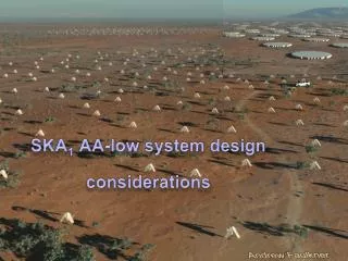
SKADS – (IRA-INAF) AAVP WP5 AA-lo AAVP (AA-lo2) Experience from SKADS-BEST (UHF) (1400 sqm) Experience from a VHF prototype. (800 sqm) This is the point we start from….
General Specifications about AAlo architecture • Face up the AAlo architecture problems: • Reduce Costs • Reduce Complexity • Increase Reliability • Increase Maintainability • Study the crucials parts • Antennas • Minimizing the cabling from Front End to Receiver/Digital Acquistion System • ........ perhaps it is worth putting a single sensor to save money...... • Very Scalable System • Modular System • Easy to replicate all parts • Design for deployment
AAVP WP5 AAlo • Antenna and Front End: LNA+ post amplifiers +Analogue Optical Transmitter supplied with solar panel. • Digital Station: Analogue Optical RXs, Power amplifications, ADCs, Digital boards inside a shielded shelter. In order to reduce the digital electronic, an analogue beamformer could be considered. SelfpoweredFE+Optical Link Galvanic isolation between FE and DS, more stable amplitude&phase Vs temperature so easy to deploy it (not necessary to bury the FO), RFI immunity, no DC power losses on the cable, no Gain disequalization.
AAlo basic block diagram Shelter Sync. Handl. Word reduction Box Outdoor Polyphase Filter Bank Filt. A A/D Pol 1 Tx Rx LNA A Cal. RFI Local Pre Proces. 2x730mW 70– 450 MHz Polyphase Filter Bank A/D Pol 2 Filt. A Tx Rx LNA A Cal. RFI Cal. RFI Packet. Fast Digital Link to tick Data processing Small Solar Panel
AAlobasic block diagram Shelter Sync. Handl. Word reduction Rx A Box Outdoor Polyphase Filter Bank Rx A A/D Pol 1 Filt. A Tx Cal. RFI Rx LNA A Local Pre Proces. 2x730mW 70– 450 MHz Polyphase Filter Bank Rx A A/D Pol 2 Filt. A Tx Rx LNA A Cal. RFI Cal. RFI Packet. Rx A Small Solar Panel Fast Digital Link to tick Data processing
Antenna task Technical talk Antenna Giuseppe and about the Ta calculation Federico • FrequencyRange: 70-450 MHz • Dual Linear Polarization • Maximum cross polarization at zenith < -20 dB • Impedance Matching 50 – 75 Ohm • Maximumlength: 2 m • Optimize the performances from 260 to 450 MHz • Directivity has to be maximized in the scanning range from 0° to 45° (required skycoverage) • No Balunisrequiredtoconnect the LNA • No groundplane • Designedfordeployment
Number of Antennas Ta calculatorallowsustoevaluate Antenna Temperature which include ground&skycontribution (preliminaryresults) Ta =1757K@70MHz113K@230MHz70K@450MHz Considering Aeff/Tsys=2000 as MEMO 125 Specs optimized for different frequency 3.3M 1.5M H Plane 0.96M
Analogue VCSEL link Ultra low cost and low power consumption devices are required for AAlo system. In the INAF AAlo design the antenna signals are sent to a local processing node (called digital station) through analogue optical links (70-450MHz) in the range of max 500mt (requested SFDR: 50dB RIN=107dB/Hz2/3) Collaboration with IEIIT-CNR Turin PierluigiDebernardi VCSEL designer Device under investigation: 850nm (single and multi mode) and 1300nm (single mode) Optical fibre under investigation: multimode (62.5um, OM3 50um) and standard single mode (9/125). Test bed: BEST-2 and BEST-3lo systems. This way we will be able to compare the VCSEL links with standard coax DFB 1300nm links in a real environment and with real astronomical observations.
AA-lo FE rough estimation of the power consumption • LNA= 360mW 2 X 3V (Vds) x 60mA (Ids) • RF Drivers = 500mW 2X 5V x 50mA • VCSEL TX-O = 50mW 2X 3V x 8mA • Front End Total = 910mW Wide Band sensor Optical fibre Filt. A Tx LNA Box Outdoor 70– 450 MHz
Reliability: ElectricalFieldMeter LightningProtection TransitofStormClouds 20/06/2010 - Medicina
2011 Italian AAlo plan The IEIIT Torino group is refining the current design of the challenging 3 octaves double polarization antenna with the required performances. Extensive station simulations required and checked. At IRA Mechanical construction of the designed antenna then test to verify performances (ONE element). The IEIIT /IRA group is facing the design of Analogue Optical TX-RX based on VCESEL technology to reduce costs and power consumption. IRA simulation, design and test of LNA low power matched to the designed antenna.COTs devices will be taken into account. A complete FE will be built in order to supply it with commercial solar panel. IRA/UNIFI test of a complete Front End considering the Design for reliability.
Conclusions • International collaboration between different group must be estabilsh to reduce efforts and sharing expertise • A common method to compare the different approches should be developed • On field tests
Any questions? Merry Christmas & Happy New Year from Italian Team
4.3M E Plane 3.7M 2.45M