Digital Data Transmission
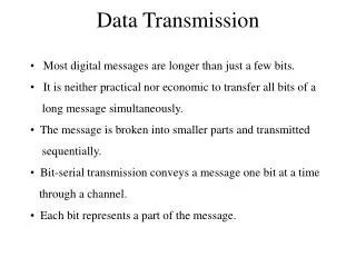
Digital Data Transmission. ECE 457 Spring 2005. Information Representation. Communication systems convert information into a form suitable for transmission Analog systems Analog signals are modulated (AM, FM radio) Digital system generate bits and transmit digital signals (Computers)


Digital Data Transmission
E N D
Presentation Transcript
Digital Data Transmission ECE 457 Spring 2005
Information Representation • Communication systems convert information into a form suitable for transmission • Analog systemsAnalog signals are modulated (AM, FM radio) • Digital system generate bits and transmit digital signals (Computers) • Analog signals can be converted to digital signals.
Components of Digital Communication • Sampling: If the message is analog, it’s converted to discrete time by sampling. (What should the sampling rate be ?) • Quantization: Quantized in amplitude. Discrete in time and amplitude • Encoder: • Convert message or signals in accordance with a set of rules • Translate the discrete set of sample values to a signal. • Decoder: Decodes received signals back into original message
Performance Metrics • In analog communications we want, • Digital communication systems: • Data rate (R bps) (Limited) Channel Capacity • Probability of error • Without noise, we don’t make bit errors • Bit Error Rate (BER): Number of bit errors that occur for a given number of bits transmitted. • What’s BER if Pe=10-6 and 107 bits are transmitted?
Advantages • Stability of components: Analog hardware change due to component aging, heat, etc. • Flexibility: • Perform encryption • Compression • Error correction/detection • Reliable reproduction
Digital Audio Transmission Telephone channels Lowpass filter,sample,quantize 32kbps-64kbps (depending on the encoder) Digital Audio Recording LP vs. CD Improve fidelity (How?) More durable and don’t deteriorate with time Applications
Each T-second pulse is a bit. • Receiver has to decide whether it’s a 1 or 0 ( A or –A) • Integrate-and-dump detector • Possible different signaling schemes?
Receiver Preformance • The output of the integrator: • is a random variable. • N is Gaussian. Why?
Analysis • Key Point • White noise is uncorrelated
Error Analysis • Therefore, the pdf of N is: • In how many different ways, can an error occur?
Error Analysis • Two ways in which errors occur: • A is transmitted, AT+N<0 (0 received,1 sent) • -A is transmitted, -AT+N>0 (1 received,0 sent)
Similarly, • The average probability of error:
Energy per bit: • Therefore, the error can be written in terms of the energy. • Define
Recall: Rectangular pulse of duration T seconds has magnitude spectrum • Effective Bandwidth: • Therefore, • What’s the physical meaning of this quantity?
Error Approximation • Use the approximation
Example • Digital data is transmitted through a baseband system with , the received pulse amplitude A=20mV. a)If 1 kbps is the transmission rate, what is probability of error?
b) If 10 kbps are transmitted, what must be the value of A to attain the same probability of error? • Conclusion: Transmission power vs. Bit rate
Amplitude Shift Keying (ASK) • 00 • 1Acos(wct) • What is the structure of the optimum receiver?
Error Analysis • 0s1(t), 1s2(t) in general. • The received signal: • Noise is white and Gaussian. • Find PE • In how many different ways can an error occur?
Error Analysis (general case) • Two ways for error: • Receive 1 Send 0 • Receive 0Send 1 • Decision: • The received signal is filtered. (How does this compare to baseband transmission?) • Filter output is sampled every T seconds • Threshold k • Error occurs when:
are filtered signal and noise terms. • Noise term: is the filtered white Gaussian noise. • Therefore, it’s Gaussian (why?) • Has PSD: • Mean zero, variance? • Recall: Variance is equal to average power of the noise process
The pdf of noise term is: • Note that we still don’t know what the filter is. • Will any filter work? Or is there an optimal one? • Recall that in baseband case (no modulation), we had the integrator which is equivalent to filtering with
The input to the thresholder is: • These are also Gaussian random variables; why? • Mean: • Variance: Same as the variance of N
Distribution of V • The distribution of V, the input to the threshold device is:
Probability of Error • Two types of errors: • The average probability of error:
Goal: Minimize the average probability of errror • Choose the optimal threshold • What should the optimal threshold, kopt be? • Kopt=0.5[s01(T)+s02(T)]
Observations • PE is a function of the difference between the two signals. • Recall: Q-function decreases with increasing argument. (Why?) • Therefore, PE will decrease with increasing distance between the two output signals • Should choose the filter h(t) such that PE is a minimummaximize the difference between the two signals at the output of the filter
Matched Filter • Goal: Given , choose H(f) such that is maximized. • The solution to this problem is known as the matched filter and is given by: • Therefore, the optimum filter depends on the input signals.
Error Probability for Matched Filter Receiver • Recall • The maximum value of the distance, • E1 is the energy of the first signal. • E2 is the energy of the second signal.
Therefore, • Probability of error depends on the signal energies (just as in baseband case), noise power, and the similarity between the signals. • If we make the transmitted signals as dissimilar as possible, then the probability of error will decrease ( )
ASK • The matched filter: • Optimum Threshold: • Similarity between signals? • Therefore, • 3dB worse than baseband.
PSK • Modulation index: m (determines the phase jump) • Matched Filter: • Threshold: 0 • Therefore, • For m=0, 3dB better than ASK.
FSK • Probability of Error: • Same as ASK
Applications • Modems: FSK • RF based security and access control systems • Cellular phones