Download
1 / 22
480 likes | 1.17k Vues
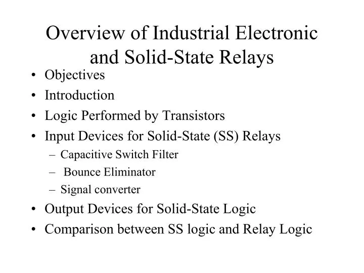
Overview of Industrial Electronic and Solid-State Relays. Objectives Introduction Logic Performed by Transistors Input Devices for Solid-State (SS) Relays Capacitive Switch Filter Bounce Eliminator Signal converter Output Devices for Solid-State Logic

E N D
Overview of Industrial Electronic and Solid-State Relays • Objectives • Introduction • Logic Performed by Transistors • Input Devices for Solid-State (SS) Relays • Capacitive Switch Filter • Bounce Eliminator • Signal converter • Output Devices for Solid-State Logic • Comparison between SS logic and Relay Logic
Objectives • To Introduce an Industrial control system and its main parts. • To describe how relays can be used to make decisions. • To distinguish between NO and NC relay contacts. • To introduce solid-state relays. • To name and explain the operation of different circuits used for input and output signal conditioning in solid-state logic. • To compare the solid-state logic to magnetic relay logic.
1.Introduction Figure 1-1. Block Diagram of an Industrial Control System
Three parts of an industrial electronic system: • 1. Input Section (Information gathering): e.g. pushbuttons, limit switches, pressure switches and photocells. • 2. Logic Section (Decision-making): e.g. magnetic relays, solid-state relays. • 3. Output Section (Activating devices): e.g. motor starter, solenoid valve, cylinder.
A relay is an electrically operated switch. Many relays use an electromagnet to operate a switching mechanism mechanically, but other operating principles are also used • Relays are used where it is necessary to control a circuit by a low-power signal (with complete electrical isolation between control and controlled circuits), or where several circuits must be controlled by one signal. • A type of relay that can handle the high power required to directly control an electric motor or other loads is called a contactor. • Solid-state relays control power circuits with no moving parts, instead using a semiconductor device to perform switching. Relays with calibrated operating characteristics and sometimes multiple operating coils are used to protect electrical circuits from overload or faults; in modern electric power systems these functions are performed by digital instruments still called "protective relays".
Simple electromagnetic relay schematic 2.Electromagnetic Relays (EMRs) • An EMR generates electromagnetic force when input voltage is applied to the coil. The electromagnetic force moves the armature that switches the contacts in synchronization. EMRs are not only mounted to control panels, but also used for a wide range of applications. The principle of the operation of EMRs is simple and it is possible to manufacture EMRs at low costs
Figure 1–2 A relay logic circuit in which the relay coil is controlled by input devices, namely a limit switch and a pressure switch.
In figure 1-2, the relay RA will be energized (picked up, picked) if LS1 closed and at the same time the PS4 is closed. • If either or both of switches are open, then RA will be deenergized (dropped out, dropped). • If RA is dropped, the contacts controlled by RA revert to their normal state. (Normally closed (NC) contacts are closed and normally open (NO) contacts are open). • If RA is picked, all contacts will change state. The NO will close and the NC will open.
Figure 1–3 A relay logic circuit in which relay coils are controlled by the contacts of other relays.
3.Logic Performed by Transistors (SSRs) • In solid-state logic, instead of contacts being open or closed, input lines are LO or HI. • In figure 1-6(a), the X line going HI (+5V) is equivalent to closing RX contact. • The X line being LO (0V or GND) is equivalent to having the RX contact open. The same is true for Y and Z. if one or more inputs is LO the output W will be LO. The output will be HI only when all inputs are HI. (AND action) • In figure 1-6(b), if any one of the inputs (X,Y,Z) goes HI, Q1 will turn ON and its ollecter will be pulled down to ground (GND), therefore no base current to Q2 which will turn OFF allowing the output W to go HI. If all inputs are LO the ouput W will be LO. (OR action)
Figure 1–6 (a) The AND logic function performed by relay circuitry and by solid-state circuitry. (b) The OR function performed by relay circuitry and by solid-state circuitry.
4. Input Devices for Solid-State Relays • Mechanical switches (LS1, LS2 in figure below) never make clean contact closure. The contact surfaces always bounce against each other several times before they make permanent closure. This problem is called contact bounce (see figure 1-9). • To eliminate the effect of this problem, we can install a capacitive switch filter or build bounce eliminator between the switch and logic gate.
V Figure 1–9. The problem of contact bounce. Bounce time (t2-t1) usually in milliseconds. The unwarranted turning ON and OFF can cause serious malfunctions in logic circuits.
4.a. Capacitive Switch Filter • The filter in figure 1-10 (a) takes the bouncing input and turn it into a smooth output which will be the input to the logic gate. • When the switch first closes the capacitor start charging but only for very small amount (which will not be enough to affect the logic gate) because the switch opens again. This is repeated for the bouncing time (t2-t1). When the switch close for permanent, the capacitor charge to the threshold voltage of the logic gate and turn it ON. • This filter also serves to reject high frequency noise signals coming to the gate from external sources thru the switch lead..
Main Gate Figure 1–10(a) RC switch filter to eliminate the effects of contact bounce. (b) Bounce eliminator built with solid-state gates.
4.b. Bounce Eliminators • Figure 10 (b) shows another method to eliminate the contact bounce effect. The main gate turns ON by the first bounce instead of waiting for the final closure. After it turns ON it ignore the subsequent bounces. • With the input switch released, the N.C. contact is closed and a HI level is applied to the R2 of NOR2 which will give LO output which in turns gives HI output for NOR1 (input1 is LO). This HI output of NOR1 is inverted by the inverter I to keep the main gate input at LO. • For switching procedure from LO to HI refer to text book page 15-16. • The disadvantage of the eliminator is that it requires a double-throw switch instead of a single N.O. contact.
4.c.Signal Converters Figure 1–11Signal converters for converting high-voltage input signals to low-voltage logic signals.
Figure 1–12 (a) Output converter, which uses a transformer to isolate the logic circuit from the input circuit. (b) Signal converter, which uses a reed relay to isolate the logic circuit from the input circuit.
5. Output Devices for Solid-State Logic Figure 1–13 Output amplifiers for amplifying low-power logic signals into high-power output signals.
5.a. Output Amplifier Using Power Transistor 5.b. Output Amplifier Using Relay Contact Figure 1–14(a) Output amplifier using a power transistor to control the current through the output device. (b) Output amplifier using a relay contact to control the current through the output device.
6. Advantages of SS Relays Over EM Relays SSRs (Solid State Relays) have no movable contacts. SSRs are not very different in operation from mechanical Relays that have movable contacts. SSRs, however, employ semiconductor switching elements, such as thyristors, triacs, diodes, and transistors.. SSRs consist of electronic parts with no mechanical contacts. Therefore, SSRs have a variety of features that mechanical relays do not incorporate. The greatest feature of SSRs is that SSRs do not use switching contacts that will physically wear out. SSRs are ideal for a wide range of applications due to the following performance characteristics. • They provide high-speed, high-frequency switching operations. • They have no contact failures. • They generate little noise. • They have no operation noise.
Comparison between S-S Relay logic and Magnetic Relay Logic. See Text book page 21-22.