Download
1 / 15
150 likes | 280 Vues
Punch-through Protection of SSDs in Beam Accidents. H. F.–W. Sadrozinski with C. Betancourt, A. Bielecki, Z. Butko, A. Deran, V. Fadeyev, S. Lindgren, C. Parker, N. Ptak, S. Sattari, J. Wright SCIPP, Univ. of California Santa Cruz, CA 95064 USA.

E N D
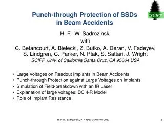
Punch-through Protection of SSDsin Beam Accidents H. F.–W. Sadrozinski with C. Betancourt, A. Bielecki, Z. Butko, A. Deran, V. Fadeyev, S. Lindgren, C. Parker, N. Ptak, S. Sattari, J. Wright SCIPP, Univ. of California Santa Cruz, CA 95064 USA • Large Voltages on Readout Implants in Beam Accidents • Punch-through Protection against Large Voltages on Implants • Simulation of Field-breakdown with an IR Laser • Explanation of large voltages: DC 4-R Model • Role of Implant Resistance H. F.-W. Sadrozinski, PTP RD50 CERN Nov 2010
Damage from Beam Losses to AC-coupled SSD • ALEPH at LEP observed break-down of the coupling capacitors on AC-coupled SSD in a beam accident. The Al readout trace of AC coupled sensors are held at ground by the readout ASIC. • We proposed that this was due to the breakdown of the field inside the sensor when the deposited charge made the sensor conductive. At that point, the bias voltage can reach into the sensor bulk and can impart large voltages to the implants. • To check this, we used IR lasers to mimic the beam loss and we indeed observed large voltages on the implants T. Dubbs et al., IEEE Trans. Nuclear Science 47, 2000:1902 – 1906. • The reach-through (punch-through) effect was considered an elegant and effective way to limit the voltages on the implants. Special punch-through protection (PTP) structure can be designed where the geometrical layout determines the voltage limits on the implants. J. Ellison et al., IEEE Trans. Nuclear Science, 36, 1989: 267 - 271. • PTP structures were implemented in the p-on-n SCT sensors. • But the PTP structure in SCT sensors were shown not to guarantee protection against large voltages across the coupling capacitors when IR laser pulses were used. K. Hara, et al., Nucl. Instr. and Meth. A 541 (2005) p. 15-20. H. F.-W. Sadrozinski, PTP RD50 CERN Nov 2010
PTP in Upgrade Sensors ATLAS07 N-on-P full-size sensors and “mini’s” to investigate PTP (in Zone 4A-4D) Y. Nobu, et al., NIMA A (2010)doi:10.1016/j.nima.2010.04.080 No PTP structure PTP structures BZ4A BZ4B BZ4C BZ4D H. F.-W. Sadrozinski, PTP RD50 CERN Nov 2010
PTP Structure Effectiveness • The effectiveness of PTP structures is determined in DC i-V measurements between the strip and the bias ring. One measures the “integral” effective resistance Reff, which is the bias resistor Rbias in parallel to the PTP resistor RPTP. • The measure of the effectiveness of the PTP structure is the punch-through voltage VPT , defined as the voltage at which RPTP = Rbias, i.e. Reff, = 0.5* Rbias . • The PT voltage VPT was measured to be a few 10’s of Volt. S. Lindgren, et al., NIM A (2010) doi:10.1016/j.nima.2010.04.094 But: VPT shows very little variation with the dimension of the PTP structure (channel length L): H. F.-W. Sadrozinski, PTP RD50 CERN Nov 2010
Testing Large Implant Voltages with Laser T. Dubbs et al., IEEE Trans. Nuclear Science 47, 2000:1902 – 1906. • Alessi IR cutting laser deposits large amounts of charge inside the detector which collapses the field(>1010 e/h pairs ~ 106 MIPs ~ 1 Rad / pulse). • Intensity given by number of laser triggers ~ 4 msec apart (we used up to 3). • Bias ring is held to ground • Voltage on a DC pad and/or AC pad are read via an high impedance voltage divider into pico-probe or digital scope. • DC pad reflects biasing of strips, • AC pad reflects instantaneous collected charge ( ~ depleted region) • Laser spot ~ 10 mm, but large DC voltages extend over few mm. • Peak voltage independent of laser intensity, and AC grnd/floating Voltages on strips are large, much larger than DC VPT, comparable to bias voltage. H. F.-W. Sadrozinski, PTP RD50 CERN Nov 2010
Laser implant voltages near RPT vs. Bias DC VPT At high bias voltages,implant voltages for PTP structures saturate.But the ones without PTP structures do not saturate (even though DC VPT were very similar) Can this be reconciled with the DC voltage dependence of RPT ? H. F.-W. Sadrozinski, PTP RD50 CERN Nov 2010
DC Characteristics of PTP Structures Extend the DC measurements to larger voltages and currents. Reff vs. Vnear Reff vs. PT current iPT RPT never becomes a short Reff = 20 kW reached at different voltages for different structures. Strip Voltage depends on resistance of bulk and implant. Reff ~ 1/ iPT Independent of structure! Reff = 10 kW reached at current of about 10 mA . H. F.-W. Sadrozinski, PTP RD50 CERN Nov 2010
Space-Charge Limitation in PTP Structures J.l. Chu, G. Persky, and S.M. Sze, J. Appl. Phys., Vol. 43, No.8, August 1972 J. Lohstroh et al. Solid-State Electronics. Vol. 24, No. 9, pp. 805-814, 1981 IPT vs. VPT SCL I ~ V Punch-Through I ~exp(V) Punchthrough Region: IPT ~ exp(V), Rpt ~ 1/iPT, VPT saturates SCL Region: iPT~ V, Rpt ~ const1/iPT+const2, RPT saturates H. F.-W. Sadrozinski, PTP RD50 CERN Nov 2010
More evidence for SCL RPT ~ 1 / iPT for all PTP structures, …but saturation of RPT at ~ 40kW for BZ2 and BZ3 SCL Region: RPT ~ const1 / iPT+ 40kW H. F.-W. Sadrozinski, PTP RD50 CERN Nov 2010
Comparison between RPT(near) and RPT(far) Difference of “identical” near and far resistances in BZ2 and BZ3: Strong gate effect of the Poly bias resistor (c.f. FOXFET) Also: in BZ4A the Poly resistor has the best channel coverage H. F.-W. Sadrozinski, PTP RD50 CERN Nov 2010
Propose a DC “4R” Model • After breakdown of field inside the sensor, deal with DC resistor chain only RPTnear = Reff (RPTnear ,Rbias ) RPTfar = RPT on the far end of the strip, RPTfar > RPTnear Rimp = Resistance of implant 15kW/cm Rbulk = Bulk Resistance To check 4R Model: Fire laser both near and far. Measure both Vnear and Vfar Calculate Vnear = Vfar- Rimmp*Inear Current regulates the punch-through resistance through RPT ~ 1 / iPT What about bulk resistance? Voltages near RTP structures clamped independent of laser position H. F.-W. Sadrozinski, PTP RD50 CERN Nov 2010
Bulk Resistance One more parameter after breakdown: Bulk resistance measured consistently Rb ≈ 15 kW (independent of the current) An approximately constant bulk resistance Rb ≈ 15 kW and a PTP resistance depending on the inverse of the current RPT ~ 1 / IPT can explain the saturation of the PTP voltages. H. F.-W. Sadrozinski, PTP RD50 CERN Nov 2010
Effect of Finite Implant Resistance Rimp Fire laser at the far end of the 1 cm strip, measure both Vnear and Vfar Vfar > Vnear Saturation in Vnear No saturation in Vfar RTP structure not effective for Vfar Limitation of application of PTP structures: finite Rimp Implant Voltages do not saturate at high bias voltages, if finite implant resistance Rimp isolates PTP structure from breakdown region. H. F.-W. Sadrozinski, PTP RD50 CERN Nov 2010
Conclusions • An IR cutting laser simulates the beam accident conditions: large Q, collapsing E-field. • Field breakdown size ~ 0.5 mm, with a much larger area with partial breakdown . • Voltages on the implants V > VPTP (DC), due to finite RPTP. • The observed voltages can be explained by 4 resistor DC model : • RPTP(near), RPTP(far), Rbulk, Rimplant. • For PTP structures, the voltage near the laser VPTP(laser, near) saturates. • Then RPTP ~20kW; I ~ 5 -10 mA. • Saturation voltage V = 50 – 100V • RPTP ~ 1 / iPT, while Rbulk ~15kW. For no PTP structure, RPTP saturates at ~ 40kW (SCL region) • Rimplantis very important: the present value, ~15 kW/cm, can effectively isolate the collapsed field from the PTP structure, increasing voltages on the implants by 100’s of volts => need low Rimplant! • The effect of the R-C biasing network at the backplane will be studied next. 2010/11/02 H. F.-W. Sadrozinski, PTP RD50 CERN Nov 2010 14
Acknowledgements The early work on the PTP measurements on ATLS07 sensors from HPK was shared within the ATLAS Upgrade Collaboration with: Y. Unno, S. Terada, Y. Ikegami, T. Kohriki, S. Mitsui Inst. of Particle and Nuclear Study, KEK, Oho 1-1, Tsukuba, Ibaraki 305-0801, Japan K. Hara, N. Hamasaki, Y. Takahashi, Univ. of Tsukuba, Inst. of Pure and Applied Sciences, Tsukuba, Ibaraki 305-9751, Japan A. Chilingarov, H. Fox Physics Department, Lancaster University, Lancaster LA1 4YB, United Kingdom H. F.-W. Sadrozinski, PTP RD50 CERN Nov 2010